This set of Engineering Drawing Multiple Choice Questions & Answers (MCQs) focuses on “Basic Principles in Dimensioning -1”.
1. The advised position of placement of the dimensions should be ______
a) Inside the view
b) Outside the view
c) On the boundaries of the view
d) Cutting the view
View Answer
Explanation: It is advised to place the dimensions outside the view. This will bring a clear picture of the view and will help in the understanding of the dimensions. Placing the dimensions outside the view gives a cleaner look.
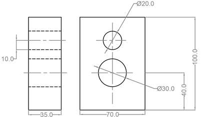
2. From the following figure, which is the repetitive dimension?
a) 30
b) 70
c) 10
d) 20
View Answer
Explanation: From the front view it is clear that the circle has diameter 20 mm. Hence its radius will be 10mm. The dimension 10mm in the side view is just a repetition of this information. Repetitive dimensions are redundant and they need to be avoided.
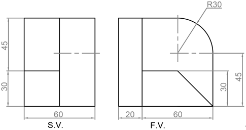
3. Which of the following dimensions is arranged haphazardly?
a) 45 in S.V.
b) 45 in F.V.
c) 30 in S.V.
d) 30 in F.V.
View Answer
Explanation: The dimension 30mm is repeated and is placed in a haphazard manner. There is no need for the dimension in F.V. as it is clearly understood from the S.V. Such dimensions should be avoided at all costs.
4. If there is a need for the center line, then it can be used as a _____
a) Dimension line
b) Leader line
c) Extension line
d) Section line
View Answer
Explanation: The center line can be used as an extension line. With the help of the center line as an extension line, we can dimension the distance between the centers of the circles from the outline view of the object. This helps in drawing the circle accurately.
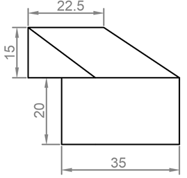
5. Which of the following dimension is incorrect?
a) 22.5
b) 15
c) 20
d) 35
View Answer
Explanation: The dimension 20mm is given without using the extension line. The outline of the view is used to dimension the line. This is not usually favoured. Always use extension line and place the dimension line in between the extension lines.
6. Dimension lines should not intersect each other as far as possible.
a) True
b) False
View Answer
Explanation: Dimension should never intersect each other as far as possible. Intersecting dimension lines can cause confusion and needs more effort to understand them. To increase the readability of the dimension they should not intersect with each other.
7. Different units of measurement can be used in dimensioning a view.
a) True
b) False
View Answer
Explanation: All dimensions should be expressed in one unit. Using different units for dimensions will create confusion for the observer and there is a chance of misinterpretation. Therefore, using different units should be avoided and a tag ‘All dimensions are in mm’ should be added above the title page.
8. While dimensioning a cylinder in the view where the true shape of the cylinder is not visible, which symbol is used to denote that it is a cylinder?
a) •
b) φ
c) ϴ
d) ○
View Answer
Explanation: Since the true shape of the cylinder is a circle from one view, we used the symbol φ followed by the dimension figure while dimensioning it in the view where it is seen as a rectangle. The cross-section of the rectangle is square then the symbol • followed by the dimension figure is used.
9. As far as possible, the dimension should be given to which of the following lines?
a) Outline
b) Hidden line
c) Center line
d) Leader line
View Answer
Explanation: Dimensions are given to the outlines of the view. It is advised not to dimension hidden lines as their true shape is not known when they hidden. It is important to dimension those lines whose true shape is properly visible.
10. How is a spot face hole with 24mm diameter, 5mm deep and spot face diameter 10mm dimensioned?
a) Φ24 and φ10
b) 5 SPOT FACE, φ24 X φ10
c) φ24 SPOT FACE, φ10
d) φ10 SPOT FACE, φ24 x 5 DEEP
View Answer
Explanation: Holes made by spot facing are dimensioned in this manner ‘φ10 SPOT FACE, φ24 x 5 DEEP’. This means the there is a spot face of 10mm diameter after the 24mm diameter and 5 mm thickness. Using this makes the reading of the dimension easy.
Sanfoundry Global Education & Learning Series – Engineering Drawing.
To practice all areas of Engineering Drawing, here is complete set of 1000+ Multiple Choice Questions and Answers.
If you find a mistake in question / option / answer, kindly take a screenshot and email to [email protected]
