This set of Engineering Drawing Multiple Choice Questions & Answers (MCQs) focuses on “Isometric Drawing of Prisms and Pyramids”.
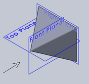
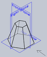
1. Identify the front view from the isometric view for the below given pyramid.

a)
b) 
c) 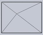
d) 
View Answer
Explanation: The isometric view should be drawn according to the given views and in such a way that maximum possible details are visible. Arrow mark in the given figure show the direction in which front is taking and dotted lines represent hidden edges and lines.
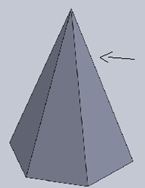
2. Identify the top view from the isometric view for the below given pyramid.

a)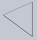
b) 
c) 
d) 
View Answer
Explanation: The isometric view should be drawn according to the given views and in such a way that maximum possible details are visible. Arrow mark in the given figure show the direction in which front is taking and dotted lines represent hidden edges and lines.
3. Identify the back view from the isometric view of the following pyramid.
a)
b) 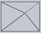
c) 
d) 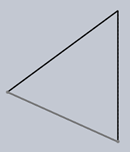
View Answer
Explanation: The isometric view should be drawn according to the given views and in such a way that maximum possible details are visible. Arrow mark in the given figure show the direction in which front is taking and dotted lines represent hidden edges and lines.
4. Identify the front view of the below given pyramid.

a) 
b) 
c)
d)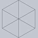
View Answer
Explanation: The isometric view should be drawn according to the given views and in such a way that maximum possible details are visible. Arrow mark in the given figure show the direction in which front is taking and dotted lines represent hidden edges and lines.
5. Identify the top view of the below given pyramid.
a)
b)
c)
d)
View Answer
Explanation: The isometric view should be drawn according to the given views and in such a way that maximum possible details are visible. Arrow mark in the given figure show the direction in which front is taking and dotted lines represent hidden edges and lines.
6. Identify the side view of for the below given pyramid.
a) 
b) 
c)
d)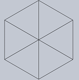
View Answer
Explanation: The isometric view should be drawn according to the given views and in such a way that maximum possible details are visible. Arrow mark in the given figure show the direction in which front is taking and dotted lines represent hidden edges and lines.
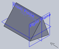
7. Identify the front view of this solid which is in isometric view.

a) 
b) 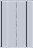
c) 
d) 
View Answer
Explanation: The isometric view should be drawn according to the given views and in such a way that maximum possible details are visible. Arrow mark in the given figure show the direction in which front is taking and dotted lines represent hidden edges and lines.
8. Identify the top view of below given solid which is in isometric view.

a) 
b) 
c) 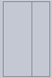
d) 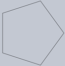
View Answer
Explanation: The isometric view should be drawn according to the given views and in such a way that maximum possible details are visible. Arrow mark in the given figure show the direction in which front is taking and dotted lines represent hidden edges and lines.
9. Identify the side view of the below given solid which is in isometric view.
a) 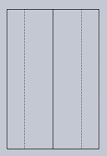
b) 
c) 
d) 
View Answer
Explanation: The isometric view should be drawn according to the given views and in such a way that maximum possible details are visible. Arrow mark in the given figure show the direction in which front is taking and dotted lines represent hidden edges and lines.
10. Identify the front view from the isometric view for the below given figure.

a) 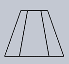
b) 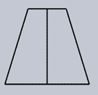
c) 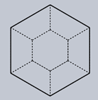
d) 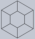
View Answer
Explanation: The isometric view should be drawn according to the given views and in such a way that maximum possible details are visible. Arrow mark in the given figure show the direction in which front is taking and dotted lines represent hidden edges and lines.
11. Identify the side view from the isometric view for the below given figure.

a) 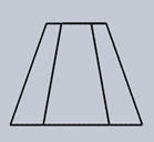
b) 
c) 
d) 
View Answer
Explanation: The isometric view should be drawn according to the given views and in such a way that maximum possible details are visible. Arrow mark in the given figure show the direction in which front is taking and dotted lines represent hidden edges and lines.
12. Identify the top view from the isometric view for the below given figure.

a) 
b) 
c) 
d) 
View Answer
Explanation: The isometric view should be drawn according to the given views and in such a way that maximum possible details are visible. Arrow mark in the given figure show the direction in which front is taking and dotted lines represent hidden edges and lines.
13. Identify the bottom view from the isometric view for the below given figure.
a) 
b) 
c) 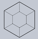
d) 
View Answer
Explanation: The isometric view should be drawn according to the given views and in such a way that maximum possible details are visible. Arrow mark in the given figure show the direction in which front is taking and dotted lines represent hidden edges and lines.
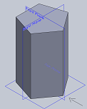
14. Identify the front view from the isometric view for the below given prism.

a)
b)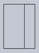
c)
d)
View Answer
Explanation: The isometric view should be drawn according to the given views and in such a way that maximum possible details are visible. Arrow mark in the given figure show the direction in which front is taking and dotted lines represent hidden edges and lines.
15. Identify the top view from the isometric view of following prism.
a)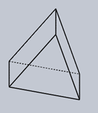
b)
c)
d)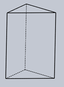
View Answer
Explanation: The isometric view should be drawn according to the given views and in such a way that maximum possible details are visible. Arrow mark in the given figure show the direction in which front is taking and dotted lines represent hidden edges and lines.
Sanfoundry Global Education & Learning Series – Engineering Drawing.
To practice all areas of Engineering Drawing, here is complete set of 1000+ Multiple Choice Questions and Answers.
If you find a mistake in question / option / answer, kindly take a screenshot and email to [email protected]
