This set of Civil Engineering Drawing Multiple Choice Questions & Answers (MCQs) focuses on “Isometric Projection”.
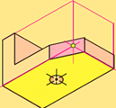
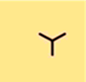
1. The following figure shows the _________ view of an object.
a) oblique
b) isometric
c) orthographic
d) perspective
View Answer
Explanation: Isometric projection is a method for visually representing three-dimensional objects in two dimensions in technical and engineering drawings. It is an axonometric projection in which the three coordinate axes appear equally foreshortened and the angle between any two of them is 120 degrees.
2. Which type of isometry does the figure below represents?
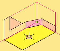
a) Multi-view
b) Regular
c) Reverse
d) Oblique
View Answer
Explanation: Reverse view is a form of perspective drawing in which the objects depicted in a scene are placed between the projective point and the viewing plane. This has the visual effect that objects farther away from the viewing plane are drawn as larger, and closer objects are drawn as smaller, in contrast to the more conventional linear perspective for which closer objects appear larger. Lines that are parallel in three-dimensional space are drawn as diverging against the horizon, rather than converging as they do in linear perspective.
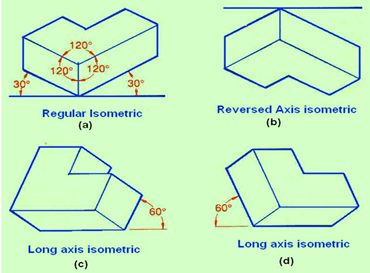
3. The three lines meeting at a point and making an angle of 1200 with each other is called_________
a) isometric axes
b) axonometric
c) orthographic axes
d) oblique axes
View Answer
Explanation: Isometric axes can be positioned in a number of ways to create different views of the same object. Figure 6(a) is a regular isometric, in which the viewpoint is looking down on the top of the object. In a regular isometric, the axes at 30° to the horizontal are drawn upward from the horizontal. In the reversed axis isometric, as shown in figure 6(b), the viewpoint is looking up on the bottom of the object, and the 30° axes are drawn downward from the horizontal. Figure 6(c) & (d) show the long axis isometric, where the viewpoint is looking from the right or from the left of the object, and one axis is drawn at 60 ° to the horizontal. While drawing the Isometric view, first the view point will have to be decided for obtaining the maximum technical information.
4. The next step after this step (shown below) for the formation of an isometric object will be______
a)
b)
c)

d)
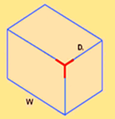
View Answer
Explanation:
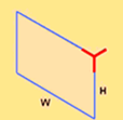
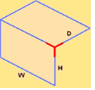
5. The figure below represents _____________
a) tree symbol
b) top and Front view
c) xyz axes
d) isometric axes
View Answer
Explanation: After determining the desired view of the object. Here the object will be viewed from above (regular isometric). The isometric axes is then drawn as shown in the figure above.
6. Here which type of isometric drawing view does the figure represents?
a) 3-Dimensional
b) Top, Front and Side
c) Multi-view drawing
d) Orthographic
View Answer
Explanation: Multi-view drawings employ multi-view projection techniques. In multi-view drawings, generally three views of an object are drawn, and the features and dimensions in each view accurately represent those of the object. Each view is a 2-D flat image. The views are defined according to the positions of the planes of projection with respect to the object.
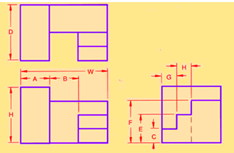
7. __________ will be the edges of inclined or oblique planes of an object as represented in a multi-view drawing.
a) Inclined lines
b) Non-isometric lines
c) Isometric lines
d) Curved lines
View Answer
Explanation: Non-isometric lines will be the edges of inclined or oblique planes of an object as represented in a multi-view drawing. It is not possible to measure the length or angle from an inclined or oblique line in a multi-view drawing and then transferring these distances to draw the line in an isometric drawing. Instead, non-isometric lines must be drawn by locating the two end points of the lines on isometric lines and then connecting these end points with a line. The process used is called offset measurement, which is a method of locating one point by projecting another point.
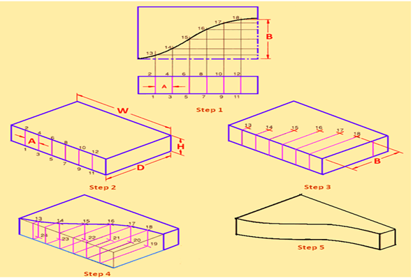
8. Figure below shows isometric view of the object having____________
a) irregular curve
b) circular curve
c) inclined curve
d) isometric curve
View Answer
Explanation: Figure showing isometric view of the object having Irregular curve
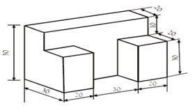
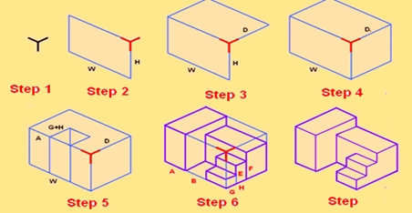
9. The isometric view of the figure will resemble what type of structure?
a) A chair
b) A staircase
c) A table
d) A column
View Answer
Explanation:
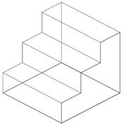
(Figure showing isometric view)
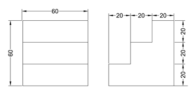
10. The shape of isometric drawing will be ______________
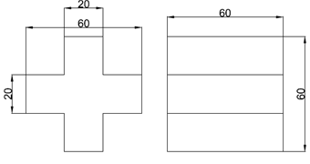
a) a plus
b) a cuboid
c) a staircase
d) a triangular prism
View Answer
Explanation:
(Figure showing isometric view)
Sanfoundry Global Education & Learning Series – Civil Engineering Drawing.
To practice all areas of Civil Engineering Drawing, here is complete set of 1000+ Multiple Choice Questions and Answers.
If you find a mistake in question / option / answer, kindly take a screenshot and email to [email protected]
- Check Civil Engineering Drawing Books
- Apply for Civil Engineering Internship
- Practice Civil Engineering MCQs
- Check Civil Engineering Books
