This set of Tough Electrical Measurements Questions and Answers focuses on “Advanced Problems on Measurement of Inductance using AC Bridges”.
1. In the Owen’s bridge shown in below figure, Z1 = 200∠60°, Z2 = 400∠-90°, Z3 = 300∠0°, Z4 = 400∠30°. Then the _______
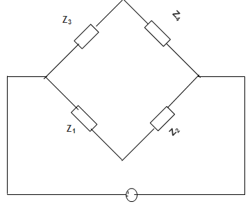
a) Bridge is balanced with given impedance values
b) Bridge can be balanced, if Z4 = 600∠60°
c) Bridge can be balanced, if Z3 = 400∠0°
d) Bridge cannot be balanced with the given configuration
View Answer
Explanation: For Bridge to be balanced, the product of impedances of the opposite arm should be equal in magnitude as well as phase angle. Here Z3 Z2 ≠ Z1 Z4 for whatever chosen value. Therefore the Bridge cannot be balanced.
2. In Maxwell’s capacitance bridge for calculating unknown inductance, the various values at balance are, R1 = 300 Ω, R2 = 700 Ω, R3 = 1500 Ω, C4 = 0.8 μF. Calculate R1, L1 and Q factor, if the frequency is 1100 Hz.
a) 240 Ω, 0.12 H, 3.14
b) 140 Ω, 0.168 H, 8.29
c) 140 Ω, 0.12 H, 5.92
d) 240 Ω, 0.36 H, 8.29
View Answer
Explanation: From Maxwell’s capacitance, we have
R1 = \(\frac{R_2 R_3}{R_4} = \frac{300 × 700}{1500}\) = 140 Ω
L1 = R2 R3 C4
= 300 × 700 × 0.8 × 10-6 = 0.168 H
Q = \(\frac{ωL_1}{R_1} = \frac{2 × π × 1100 × 0.168}{140}\) = 8.29.
3. In Wein’s bridge, the output frequency is determined by __________
a) RLC combination
b) LC combination
c) RC combination
d) RL combination
View Answer
Explanation: The frequency of Wien Bridge is given by
f = \(\frac{1}{2π(R_1 R_2 C_1 C_2 )^{0.5}}\) Hz
∴ The output frequency is determined by the RC combinations.
4. What is the disadvantage of Maxwell Bridge?
a) Inductance cannot be measured over a wide range
b) Measurement is not independent of frequency
c) Number of components is large
d) Inductance can be measured over a wide range
View Answer
Explanation: Maxwell Bridge cannot be used for the measurement of high Q values.
We have, Q = \(\frac{1}{ωR_X C_X} = \frac{ωL_X}{R_X}\)
Hence, Q ∝ LX
∴ Inductance cannot be measured over a wide range.
5. The Bridge shown in the below figure is ______________
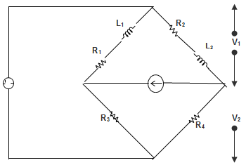
a) Maxwell’s Bridge
b) Wien’s Bridge
c) Anderson’s Bridge
d) Hay’s Bridge
View Answer
Explanation: The given figure is Maxwell’s Bridge because it consists of two inductors. It is also used to measure the inductance of the inductor.
6. Hay’s Bridge is used for measuring __________
a) Resistance in the milliohm range
b) Low values of capacitance
c) Comparison of resistances which are nearly equal
d) The Inductance of a coil with a large time constant
View Answer
Explanation: Carey – Foster slide-wire is suited for the comparison of resistances which are nearly equal. The Schering Bridge is suited for Low values of capacitance. The Kelvin double bridge is used for measuring resistance in the milliohm range. Hay’s Bridge is suited for the measurement of Inductance of a coil with a large time constant.
7. In Maxwell’s Bridge, as shown in the figure below, the values of the resistance R1 and inductance L1 of a coil are to be calculated after the bridge is balanced. The values are?
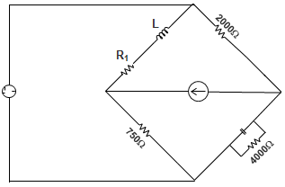
a) 375 Ω and 75 mH
b) 75 Ω and 150 mH
c) 37.5 Ω and 75 mH
d) 75 Ω and 75 mH
View Answer
Explanation: Applying the usual balance condition relation,
Z1 Z4 = Z2 Z3
We have, (R1 + jL1 ω) \(\frac{R_4/jωC_4}{R_4+1/jωC_4}\) = R2 R3
Or, R1 R4 + jL1 ωR4 = R2 R3 + j R2 R3 R4 C4 ω
∴ R1 = 2000 × \(\frac{750}{4000}\) = 375 Ω
∴ L1 = 2000 × 750 × 0.5 × 10-6
= 75 mH.
8. Maxwell’s Inductance Capacitance Bridge is used for measuring ___________
a) Inductance
b) Capacitance
c) Frequency
d) Mutual Inductance
View Answer
Explanation: For measuring Capacitance De-Sauty’s Bridge and Schering Bridge should be used. For measuring Frequency Wien’s Bridge is used. For measuring Mutual Inductance Heaviside and Campbell’s Bridge are used.
9. The four arms of an AC bridge network are as follows:
Arm AB: unknown impedance
Arm BC: standard capacitor C2 of 1000pf
Arm CD: a non-inductive resistance of R of 100 Ω in parallel to a capacitor of 0.01 μF
Arm DA: a non-inductive resistance of 1000 Ω
The supply frequency is 50 Hz and connected across terminals B and D. If the bridge is balanced with the above value, determine the value of unknown Impedance.
a) 10 kΩ
b) 100 kΩ
c) 250 kΩ
d) 20 kΩ
View Answer
Explanation: For the balance conditions,
Z1 Z3 = Z2 Z4
1000 × \(\frac{1}{jω × 1000 × 10^{-12}}\) = (R + jX) \(\frac{100}{1 + j100 × ω × 0.01 × 10^{-6}} \)
Or, \(\frac{10^{12}}{jω}\) = (R + jX) \(\frac{100}{1 + jω + 10^{-6}} \)
Or, \(\frac{- j10^{10}}{ω}\) – 104 = R + jX
Comparing the real part, we get,
R = 10 kΩ.
10. The four arms of an AC bridge network are as follows:
Arm AB: unknown impedance
Arm BC: standard capacitor C2 of 1000pf
Arm CD: a non-inductive resistance of R of 100 Ω in parallel to a capacitor of 0.01 μF
Arm DA: a non-inductive resistance of 1000 Ω
The supply frequency is 50 Hz and connected across terminals B and D. If the bridge is balanced with the above value, determine the value of unknown Capacitance.
a) 100 pf
b) 1000 pf
c) 500 pf
d) 10 pf
View Answer
Explanation: For the balance conditions,
Z1 Z3 = Z2 Z4
1000 × \(\frac{1}{jω × 1000 × 10^{-12}}\) = (R + jX) \(\frac{100}{1 + j100 × ω × 0.01 × 10^{-6}} \)
Or, \(\frac{10^{12}}{jω}\) = (R + jX) \(\frac{100}{1 + jω + 10^{-6}} \)
Or, \(\frac{- j10^{10}}{ω}\) – 104 = R + jX
Comparing the imaginary part, we get,
\(\frac{1}{ωC} = \frac{10^{10}}{ω}\)
Or, C = 100 pf.
Sanfoundry Global Education & Learning Series – Electrical Measurements.
To practice tough questions and answers on all areas of Electrical Measurements, here is complete set of 1000+ Multiple Choice Questions and Answers.
If you find a mistake in question / option / answer, kindly take a screenshot and email to [email protected]
