This set of Network Theory Multiple Choice Questions & Answers (MCQs) focuses on “Thevenin Theorem Involving Dependent and Independent Sources”.
1. A circuit is given in the figure below. The Thevenin equivalent as viewed from terminals x and x’ is ___________
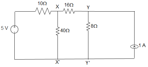
a) 8 V and 6 Ω
b) 5 V and 6 Ω
c) 5 V and 32 Ω
d) 8 V and 32 Ω
View Answer
Explanation: We, Thevenized the left side of xx’ and source transformed right side of yy’.
Vxx’ = Vth = \(\displaystyle\frac{\frac{4}{8} + \frac{8}{24}}{\frac{1}{8} + \frac{1}{24}}\) = 5V
∴ Rth = 8 || (16 + 8)
= \(\frac{8×24}{8+24}\) = 6 Ω.
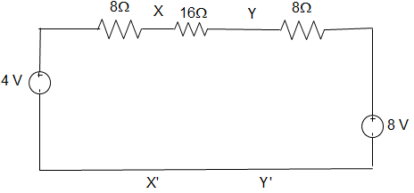
2. For the circuit given in figure below, the Thevenin equivalent as viewed from terminals y and y’ is _________
a) 8 V and 32 Ω
b) 4 V and 32 Ω
c) 5 V and 6 Ω
d) 7 V and 6 Ω
View Answer
Explanation: We, Thevenized the left side of xx’ and source transformed right side of yy’.
Thevenin equivalent as seen from terminal yy’ is
Vxx’ = Vth = \(\displaystyle\frac{\frac{4}{24} + \frac{8}{8}}{\frac{1}{24} + \frac{1}{8}}\) = 5V
= \(\frac{0.167+1}{0.04167+0.125}\) = 7 V
∴ Rth = (8 + 16) || 8
= \(\frac{24×8}{24+8}\) = 6 Ω.
3. In the following circuit, when R = 0 Ω, the current IR equals to 10 A. The value of R, for which maximum power is absorbed by it is ___________
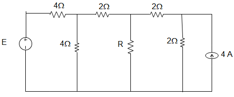
a) 4 Ω
b) 3 Ω
c) 2 Ω
d) 1 Ω
View Answer
Explanation: The Thevenin equivalent of the circuit is as shown below.
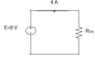
Therefore from the figure we can infer that Rth = 2 Ω
4. In the following circuit, when R = 0 Ω, the current IR equals to 10 A. The maximum power will be?
a) 50 W
b) 100 W
c) 200 W
d) 400 W
View Answer
Explanation: The Thevenin equivalent of the circuit is as shown below.
I = 10 A, Rth = 2 Ω
∴ Pmax = (\(\frac{10}{2}\))2 × 2
= 5×5×2 = 50 W.
5. For the circuit given below, the Thevenin resistance across the terminals A and B is _____________
a) 5 Ω
b) 7 kΩ
c) 1.5 kΩ
d) 1.1 kΩ
View Answer
Explanation: Let VAB = 1 V
5 VAB = 5
Or, 1 = 1 × I1 or, I1 = 1
Also, 1 = -5 + 1(I – I1)
∴ I = 7
Hence, R = 0.2 kΩ.
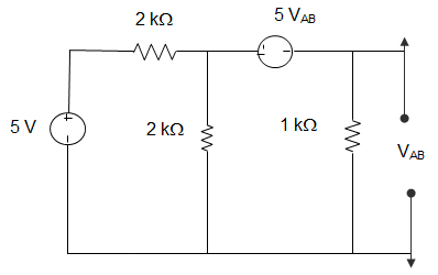
6. For the circuit given below, the Thevenin voltage across the terminals A and B is ____________
a) 1.25 V
b) 0.25 V
c) 1 V
d) 0.5 V
View Answer
Explanation: Current through 1 Ω = \(\frac{5}{2}\) – I1
Using source transformation to 5 V sources, VOC = 1 × I1
VOC = -5 VOC + (\(\frac{5}{2}\) – I1) × 1
Eliminating I1, we get, VOC = 0.5 V.
7. In the following circuit, the value of open circuit voltage and the Thevenin resistance between terminals a and b are ___________
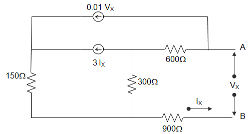
a) VOC = 100 V, RTH = 1800 Ω
b) VOC = 0 V, RTH = 270 Ω
c) VOC = 100 V, RTH = 90 Ω
d) VOC = 0 V, RTH = 90 Ω
View Answer
Explanation: By writing loop equations for the circuit, we get,
VS = VX, IS = IX
VS = 600(I1 – I2) + 300(I1 – I2) + 900 I1
= (600+300+900) I1 – 600I2 – 300I3
= 1800I1 – 600I2 – 300I3
I1 = IS, I2 = 0.3 VS
I3 = 3IS + 0.2VS
VS = 1800IS – 600(0.01VS) – 300(3IS + 0.01VS)
= 1800IS – 6VS – 900IS – 3VS
10VS = 900IS
For Thevenin equivalent, VS = RTH IS + VOC
So, Thevenin voltage VOC = 0
Resistance RTH = 90Ω.
8. In the circuit given below, it is given that VAB = 4 V for RL = 10 kΩ and VAB = 1 V for RL = 2kΩ. The values of the Thevenin resistance and voltage for the network N are ____________
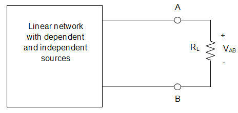
a) 16 kΩ and 30 V
b) 30 kΩ and 16 V
c) 3 kΩ and 6 V
d) 50 kΩ and 30 V
View Answer
Explanation: When RL = 10 kΩ and VAB = 4 V
Current in the circuit I = \(\frac{V_{AB}}{R_L} = \frac{4}{10}\) = 0.4 mA
Thevenin voltage is given by VTH = I (RTH + RL)
= 0.4(RTH + 10)
= 0.4RTH + 4
Similarly, for RL = 2 kΩ and VAB = 1 V
So, I = \(\frac{1}{2}\) = 0.5 mA
VTH = 0.5(RTH + 2)
= 0.5 RTH + 1
∴ 0.1RTH = 3
Or, RTH = 30 kΩ
And VTH = 12 + 4 = 16 V.
9. For the circuit shown in figure below, the value of the Thevenin resistance is _________
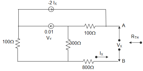
a) 100 Ω
b) 136.4 Ω
c) 200 Ω
d) 272.8 Ω
View Answer
Explanation: IX = 1 A, VX = Vtest
Vtest = 100(1-2IX) + 300(1-2IX – 0.01VS) + 800
Or, Vtest = 1200 – 800IX – 3Vtest
Or, 4Vtest = 1200 – 800 = 400
Or, Vtest = 100V
∴ RTH = \(\frac{V_{test}}{1}\) = 100 Ω.
10. For the circuit shown in the figure below, the Thevenin voltage and resistance looking into X-Y are __________
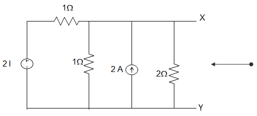
a) \(\frac{4}{3}\) V and 2 Ω
b) 4V and \(\frac{2}{3}\) Ω
c) \(\frac{4}{3}\) V and \(\frac{2}{3}\) Ω
d) 4 V and 2 Ω
View Answer
Explanation: \(R_{TH} = \frac{V_{OC}}{I_{SC}}\)
VTH = VOC
Applying KCL at node A, \(\frac{2I-V_{TH}}{1} + 2 = I + \frac{V_{TH}}{2}\)
Or, I = \(\frac{V_{TH}}{1}\)
Putting, 2VTH – VTH + 2 = VTH + \(\frac{V_{TH}}{2}\)
Or, VTH = 4 V.
∴ RTH = 4/2 = 2Ω.
11. In the figure given below, the value of the source voltage is ___________
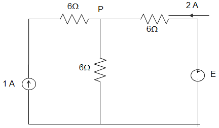
a) 12 V
b) 24 V
c) 30 V
d) 44 V
View Answer
Explanation: By applying KCL, \(\frac{V_P-E}{6} + \frac{V_P}{6}\) – 1 = 0
Or, 2 VP – E = 6
Where, (\(\frac{-V_P+E}{6}\)) = 2
∴ E – VP = 12
Or, VP = 18 V
∴ E = 30V.
12. In the figure given below, the value of Resistance R by Thevenin Theorem is ___________
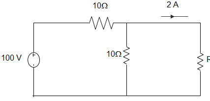
a) 10
b) 20
c) 30
d) 40
View Answer
Explanation: \(\frac{V_P-100}{10} + \frac{V_P}{10}\) + 2 = 0
Or, 2VP – 100 + 20 = 0
∴ VP = 80/2 = 40V
∴ R = 20Ω.
13. In the figure given below, the Thevenin’s equivalent pair, as seen at the terminals P-Q, is given by __________
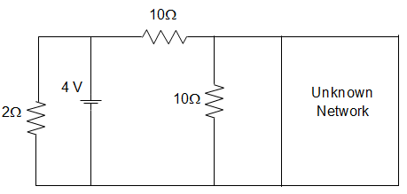
a) 2 V and 5 Ω
b) 2 V and 7.5 Ω
c) 4 V and 5 Ω
d) 4 V and 7.5 Ω
View Answer
Explanation: For finding VTH,
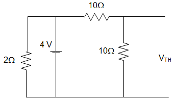
VTH = \(\frac{4 ×10}{10+10}\) = 2V
For finding RTH,
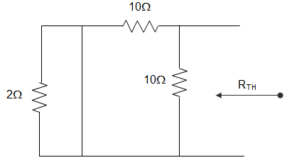
RTH = 10 || 10
= \(\frac{10×10}{10+10}\) = 5 Ω.
14. The Thevenin equivalent impedance Z between the nodes P and Q in the following circuit is __________
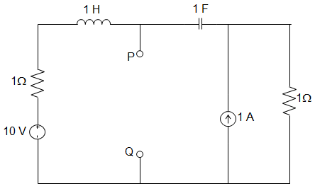
a) 1
b) 1 + s + \(\frac{1}{s}\)
c) 2 + s + \(\frac{1}{s}\)
d) 3 + s + \(\frac{1}{s}\)
View Answer
Explanation: To calculate the Thevenin resistance, all the current sources get open-circuited and voltage source short-circuited.
∴ RTH = (\(\frac{1}{s}\) + 1) || (1+s)
= \(\frac{\left(\frac{1}{s} + 1\right)×(1+s)}{\left(\frac{1}{s} + 1\right)+(1+s)}\)
= \(\frac{\frac{1}{s}+1+1+s}{\frac{1}{s}+1+1+s}\) = 1
So, RTH = 1.
15. While computing the Thevenin equivalent resistance and the Thevenin equivalent voltage, which of the following steps are undertaken?
a) Both the dependent and independent voltage sources are short-circuited and both the dependent and independent current sources are open-circuited
b) Both the dependent and independent voltage sources are open-circuited and both the dependent and independent current sources are short-circuited
c) The dependent voltage source is short-circuited keeping the independent voltage source untouched and the dependent current source is open-circuited keeping the independent current source untouched
d) The dependent voltage source is open-circuited keeping the independent voltage source untouched and the dependent current source is short-circuited keeping the independent current source untouched
View Answer
Explanation: While computing the Thevenin equivalent voltage consisting of both dependent and independent sources, we first find the equivalent voltage called the Thevenin voltage by opening the two terminals. Then while computing the Thevenin equivalent resistance, we short-circuit the dependent voltage sources keeping the independent voltage sources untouched and open-circuiting the dependent current sources keeping the independent current sources untouched.
Sanfoundry Global Education & Learning Series – Network Theory.
To practice all areas of Network Theory, here is complete set of 1000+ Multiple Choice Questions and Answers.
If you find a mistake in question / option / answer, kindly take a screenshot and email to [email protected]
