This set of Advanced Network Theory Questions and Answers focuses on “Advanced Problems on Network Theorems – 2”.
1. A network contains linear resistors and ideal voltage source s. If values of all the resistors are doubled, then voltage across each resistor is __________
a) Halved
b) Doubled
c) Increases by 2 times
d) Remains same
View Answer
Explanation: V / R ratio is a constant R. If R is doubled then, electric current will become half. So voltage across each resistor is same.
2. A voltage waveform V(t) = 12t2 is applied across a 1 H inductor for t ≥ 0, with initial electric current through it being zero. The electric current through the inductor for t ≥ 0 is given by __________
a) 12 t
b) 24 t
c) 12 t3
d) 4 t3
View Answer
Explanation: We know that, I = \(\frac{1}{L} \int_0^t V \,dt\)
= 1\(\int_0^t 12 t^2 \,dt\)
= 4 t3.
3. The linear circuit element among the following is ___________
a) Capacitor
b) Inductor
c) Resistor
d) Capacitor & Inductor
View Answer
Explanation: A linear circuit element does not change its value with voltage or current. The resistance is only one among the others does not change its value with voltage or current.
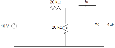
4. In the circuit shown, VC is zero at t=0 s. For t>0, the capacitor current IC(t), where t is in second, is ___________
a) 0.50 e-25t mA
b) 0.25 e-25t mA
c) 0.50 e-12.5t mA
d) 0.25 e-6.25t mA
View Answer
Explanation: The capacitor voltage VC (t) = VC (∞) – [VC (∞)-VC (0)]e-t/RC
R = 20 || 20 = \(\frac{20×20}{20+20} = \frac{400}{40}\) = 10 kΩ
VC (∞) = 10 × \(\frac{20}{20+20}\) = 5 V
Given, VC (0) = 0
∴ VC (t) = 5 – (5-0)e-t/10×4×10^(-6)×10^3
= 5(1 – e-25t)
IC (t) = C\(\frac{dV_C (t)}{dt} = 4×10^{-6} \frac{d}{dt}5(1-e^{-25t})\)
= 4 × 10-6 × 5 × 25e-25t
∴ IL (t) = 0.50e-2.5t mA.
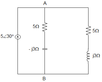
5. In the circuit given below, the phasor voltage VAB (in volt) is _________
a) Zero
b) 5∠30°
c) 12.5∠30°
d) 17∠30°
View Answer
Explanation: Equivalent impedance = (5 + j3) || (5 – √3)
= \(\frac{(5+j3)×(5 – \sqrt{3})}{(5+j3) + (5 – \sqrt{3})} \)
= \(\frac{25+9}{10}\) = 3.4 Ω
VAB = Current × Impedance
= 5∠30° × 3.4
= 17∠30°.
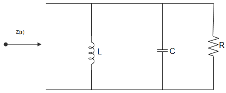
6. For the circuit given below, the driving point impedance is given by, Z(s) = \(\frac{0.2s}{s^2+0.1s+2} \). The component values are _________
a) L = 5 H, R = 0.5 Ω, C = 0.1 F
b) L = 0.1 H, R = 0.5 Ω, C = 5 F
c) L = 5 H, R = 2 Ω, C = 0.1 F
d) L = 0.1 H, R = 2 Ω, C = 5 F
View Answer
Explanation: Dividing point impedance = R || sL || \(\frac{1}{sC} \)
= \(\Big\{\frac{(R)(\frac{1}{sC})}{R + \frac{1}{sC}}\Big\}\) || sL
= \(\frac{\frac{R}{1+sRC}}{\frac{R}{1+sRC}+sL} \)
= \(\frac{sRL}{s^2 RLC+sL+R} \)
Given that, Z(s) = \(\frac{0.2s}{s^2+0.1s+2} \)
∴ On comparing, we get L = 0.1 H, R = 2 Ω, C = 5 F.
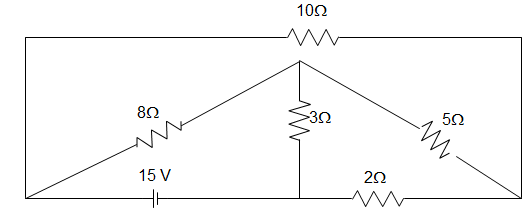
7. What is the power loss in the 10 Ω resistor in the network shown in the figure below?
a) 15.13 W
b) 11.23 W
c) 16 W
d) 14 W
View Answer
Explanation: In mesh aef, 8(I1 – I3) + 3(I1 – I2) = 15
Or, 11 I1 – 3 I2 – 8I3 = 15
In mesh efd, 5(I2 – I3) + 2I2 + 3(I2 – I1) = 0
Or, -3 I1 + 10I2 – 5I3 = 0
In mesh abcde, 10I3 + 5(I3 – I2) + 8(I3 – I1) = 0
Or, -8I1 – 5I2 +23I3 = 0
Thus loop equations are,
11 I1 – 3 I2 – 8I3 = 15
-3 I1 + 10I2 – 5I3 = 0
-8I1 – 5I2 + 23I3 = 0
Solving by Cramer’s rule, I3 = current through the 10Ω resistor = 1.23 A
∴ Current through 10 Ω resistor = 1.23 A
Power loss (P) = \(I_3^2 r\) = (1.23)2×10 = 15.13 W.
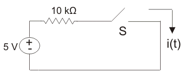
8. The switch S is the circuit shown in the figure is ideal. If the switch is repeatedly closed for 1 ms and opened for 1 ms, the average value of i(t) is ____________
a) 0.25 mA
b) 0.35 mA
c) 0.5 mA
d) 1 mA
View Answer
Explanation: Since i = \(\frac{5}{10 × 10^{-3}}\) = 0.5 × 103 = 0.5 mA
As the switch is repeatedly close, then i(t) will be a square wave.
So average value of electric current is (\(\frac{0.5}{2}\)) = 0.25 mA.
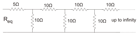
9. In the circuit given below the value of resistance, Req is ___________
a) 10 Ω
b) 11.86 Ω
c) 11.18 Ω
d) 25 Ω
View Answer
Explanation: The circuit is as shown in figure below.
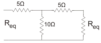
Req = 5 + \(\frac{10(R_{eq}+5)}{10 + 5 + R_{eq}}\)
Or, \(R_{eq}^2 + 15R_{eq}\) = 5Req + 75 + 10Req + 50
Or, Req = \(\sqrt{125}\) = 11.18 Ω.
10. A particular electric current is made up of two component: a 10 A and a sine wave of peak value 14.14 A. The average value of electric current is __________
a) 0
b) 24.14 A
c) 10 A
d) 14.14 A
View Answer
Explanation: Average dc electric current = 10 A
Average ac electric current = 0 A as it is alternating in nature.
Average electric current = 10 + 0 = 10 A.
11. Given that, R1 = 36 Ω and R2 = 75 Ω, each having tolerance of ±5% are connected in series. The value of resultant resistance is ___________
a) 111 ± 0 Ω
b) 111 ± 2.77 Ω
c) 111 ± 5.55 Ω
d) 111 ± 7.23 Ω
View Answer
Explanation: R1 = 36 ± 5% = 36 ± 1.8 Ω
R2 = 75 ± 5% = 75 ± 3.75 Ω
∴ R1 + R2 = 111 ± 5.55 Ω.
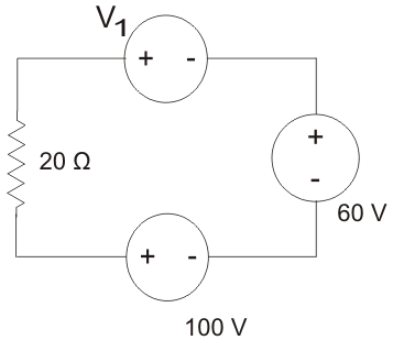
12. In the circuit of figure below a charge of 600 C is delivered to 100 V source in a 1 minute. The value of V1 is ___________
a) 30 V
b) 60 V
c) 120 V
d) 240 V
View Answer
Explanation: In order for 600 C charges to be delivered to 100 V source, the electric current must be anti-clockwise.
\(i = \frac{dQ}{dt} = \frac{600}{60}\) = 10A
Applying KVL we get
V1 + 60 – 100 = 10 × 20 ⇒ V1 = 240 V.
13. The energy required to charge a 10 μF capacitor to 100 V is ____________
a) 0.01 J
b) 0.05 J
c) 5 X 10⁻⁹ J
d) 10 X 10-9 J
View Answer
Explanation: E = \(\frac{1}{2} CV^2\)
= 5 X 10-6 X 1002
= 0.05 J.
14. Among the following, the active element of electrical circuit is ____________
a) Voltage source
b) Current source
c) Resistance
d) Voltage and current source both
View Answer
Explanation: We know that active elements are the ones that are used to drive the circuit. They also cause the electric current to flow through the circuit or the voltage drop across the element. Here only the voltage and current source are the ones satisfying the above conditions.
15. In the circuit given below, the source current is _________
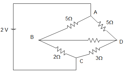
a) 2 A
b) 3 A
c) 0.54 A
d) 1.5 A
View Answer
Explanation: In the given figure, RX = RY = RZ = \(\frac{5×5}{5+5+5}\) = 1.67 Ω
Here, R = [(RX + 2) || (RY + 3)] + RX
= (3.67 || 4.67) + RZ
= \(\frac{3.67 × 4.67}{3.67 + 4.67}\) + 1.67
= \(\frac{17.1389}{8.34}\) + 1.67
= 3.725 Ω
∴ I = \(\frac{V}{R} = \frac{2}{3.725}\) = 0.54 A.
Sanfoundry Global Education & Learning Series – Network Theory.
To practice advanced questions and answers on all areas of Network Theory, here is complete set of 1000+ Multiple Choice Questions and Answers.
If you find a mistake in question / option / answer, kindly take a screenshot and email to [email protected]
