This set of Network Theory Multiple Choice Questions & Answers (MCQs) focuses on “Advanced Problems on Magnetically Coupled Circuits – 1”.
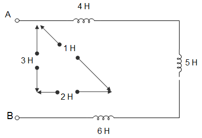
1. For the circuit given below, the effective inductance of the circuit across the terminal AB is ___________
a) 9 H
b) 21 H
c) 11 H
d) 6 H
View Answer
Explanation: LEFF across AB = L1 + L2 + L3 – 2M12 – 2M13 + 2M23
= (4 + 5 + 6 – 2 × 1 -2 × 3 + 2 × 2)
= (15 – 2 – 6 + 4)
= (15 – 8 + 4)
= (15 – 4)
= 11.
2. Two coils are having self-inductance of 5 mH and 10 mH and a mutual inductance of 0.5 mH in a differential connection. The equivalent inductance of the combination is ___________
a) 14 mH
b) 5.85 mH
c) 6 mH
d) 6.15 mH
View Answer
Explanation: When 2 coils are connected in series, then effective inductance,
LEFF = L1 + L2 ± 2M
For this case, LEFF = L1 + L2 – 2M
= 5 + 10 – 2 × 0.5
= 15 – 1
= 14 mH.
3. When two coupled coils of equal self-inductance are connected in series in one way the net inductance is 20 mH and when they are connected in the other way, the net inductance is 12 mH. The maximum value of net inductance when they are connected in parallel is __________
a) 2 mH
b) 5 mH
c) 4 mH
d) 6 mH
View Answer
Explanation: LEFF = L1 + L2 ± 2M (when the two coils are connected in series)
Now, L1 = L2 = L
∴ LEFF = 2L ± 2M
Or, 2L + 2M = 20
Or, 2L – 2M = 12
∴ L = 8, M = 2
Now, to get maximum value in parallel connection,
LMAX = \(\frac{(L+M)(L+M)}{2L+2M}\)
= \(\frac{(8+2)(8+2)}{(16+4)}\)
= \(\frac{100}{20}\) = 5 mH.
4. For 2 coupled inductors LA and LB, their mutual inductance MLALB satisfies ____________
a) MLALB = \(\sqrt{L_A^2 + L_B^2}\)
b) MLALB > \(\frac{(L_A + L_B)}{2}\)
c) MLALB > \(\sqrt{L_A L_B}\)
d) MLALB ≤ \(\sqrt{L_A L_B}\)
View Answer
Explanation: M = K \(\sqrt{L_A L_B}\)
Or, K = \(\frac{M}{\sqrt{L_A L_B}}\)
∴ K≤1
∴ \(\frac{M}{\sqrt{L_A L_B}}\) ≤ 1
Or, M ≤ \(\frac{M}{\sqrt{L_A L_B}}\).
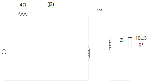
5. The impedance seen by the source in the circuit is given by __________
a) (0.54 + j0.313) Ω
b) (4 – j2) Ω
c) (4.54 – j1.69) Ω
d) (4 + j2) Ω
View Answer
Explanation: Z1 = 10∠30° × (\(\frac{1}{4}\))2
Z1 = (0.54 + j0.31) Ω
Total impedance= (4 – j2) + (0.56 + j0.31)
= (4.54 – j1.69) Ω.
6. For the circuit given below, the inductance measured across the terminals 1 and 2 was 15 H with open terminals 3 and 4. It was 30 H when terminals 3 and 4 were short-circuited. Both the inductors are having inductances 2H. The coefficient of coupling is ______________
a) 1
b) 0.707
c) 0.5
d) Inderminate due to insufficient data
View Answer
Explanation: When 2 coils are connected in series, then effective inductance,
LEFF = L1 + L2 ± 2M
For this case, LEFF = L1 + L2 – 2M
However, L1 + L2 + 2M or L1 + L2 – 2M cannot be determined.
Hence, data is insufficient to calculate the value of coupling coefficient (k).
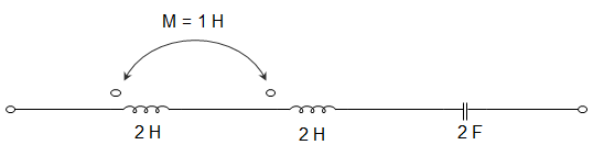
7. In the circuit given below, the resonant frequency is ________________
a) \(\frac{1}{2π\sqrt{3}}\) Hz
b) \(\frac{1}{4π\sqrt{3}}\) Hz
c) \(\frac{1}{4π\sqrt{2}}\) Hz
d) \(\frac{1}{π\sqrt{2}}\) Hz
View Answer
Explanation: LEFF = L1 + L2 + 2M
= 2 + 2 + 2 × 1
Or, LEFF = 6 H
At resonance, ωL = \(\frac{1}{ωC}\)
Or, ω = \(\frac{1}{\sqrt{L_{EFF} C}} = \frac{1}{\sqrt{12}}\)
Or, I = \(\frac{1}{4π\sqrt{3}}\) Hz.
8. The maximum value of mutual inductance of 2 inductively coupled coils with self inductance LA = 49 mH and LB = 81 mH is ______________
a) 130 mH
b) 63 mH
c) 32 mH
d) 3969 mH
View Answer
Explanation: M ≤ K\(\sqrt{L_A L_B}\)
Maximum value of (M)
Or, Mmax = K\(\sqrt{L_A L_B}\)
Or, Mmax = \(\sqrt{L_A L_B}\)
= \(\sqrt{40 ×81}\) = 63 mH.
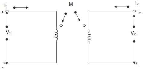
9. In the circuit shown below, I1 = 4 sin2t A and I2 = 0. The value of V1 is _______________
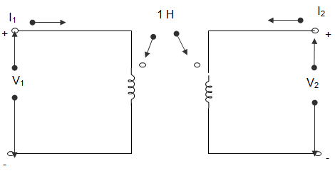
a) -16 cos2t V
b) 16 cos2t V
c) 4 cos2t V
d) -4 cos2t V
View Answer
Explanation: V1 = \(\frac{2dI_1}{dt} + \frac{1dI_2}{dt}\)
∴ V1 = \(\frac{2dI_1}{dt}\) = 16 cos2t V.
10. In the circuit shown below, I1 = 4 sin2t A and I2 = 0. The value of V2 is _______________
a) 2 cos2t V
b) -2 cos2t V
c) 8 cos 2t V
d) -8 cos2t V
View Answer
Explanation: V2 = \(\frac{dI_2}{dt} + \frac{dI_1}{dt}\)
Or, V2 = \(\frac{dI_1}{dt}\)
∴ V2 = 8 cos2t V.
11. A parallel resonant circuit has a midband admittance of 20×10-3 S, quality factor of 60 and a resonance frequency of 200 k rad/s. The value of R is _____________
a) 50 Ω
b) 56.57 Ω
c) 80 Ω
d) 28.28 Ω
View Answer
Explanation: At midband frequency, Z = R, Y = \(\frac{1}{R}\)
Or, R = \(\frac{1}{20 × 10^{-3}}\) = 50 Ω.
12. A circuit resonates at 1 MHz It also has a Q of 100. Bandwidth between half power points is _____________
a) 10 kHz
b) 100 kHz
c) 10 Hz
d) 100 Hz
View Answer
Explanation: We know that, Q = \(\frac{f}{∆f}\)
Or, ∆f = \(\frac{f}{Q}\)
= \(\frac{10^6}{100}\) = 10 kHz.
13. A series RLC circuit has R = 10 Ω, |XL| = 20 Ω and |XC| = 20 Ω is connected across an AC supply of 200 Vrms. The RMS voltage across the capacitor is ____________
a) 200∠-90° V
b) 200∠90° V
c) 400∠90° V
d) 400∠-90° V
View Answer
Explanation: Q = \(\frac{|X_L|}{R} = \frac{|X_C|}{R}\)
So, Q = \(\frac{20}{10}\) = 2
Rms voltage across capacitor, VCrms = QV∠-90°
Or, VCrms = 2 X 200∠-90°
Or, VCrms = 400∠-90° V.
14. For the circuit given below, the value of input frequency which is required to cause a gain equal to 1.5 is _____________
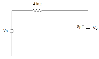
a) 20 rad/s
b) 20 Hz
c) 10 rad/s
d) No such value exists
View Answer
Explanation: H (ω) = \(\frac{V_O}{V_i}\)
= \(\frac{1}{1+jωRC}\)
∴ Gain = \(\frac{1}{\sqrt{1 + ω^2 RC}}\)
For any value of ω, R and C gain is ≤ 1.
15. Two resistances 100 ± 5Ω and 150 ± 15Ω are connected in series. If the error is specified as standard deviations, the resultant error will be ________________
a) ±10 Ω
b) ±10.6 Ω
c) ±15.8 Ω
d) ±20 Ω
View Answer
Explanation: Given, R1 = 100 ± 5 Ω
R2 = 150 ± 15 Ω
Now, R = R1 + R2
The probable errors in this case, R = ± (\(R_1^2 + R_2^2)^{0.5}\) = ± 15.8 Ω.
Sanfoundry Global Education & Learning Series – Network Theory.
To practice all areas of Network Theory, here is complete set of 1000+ Multiple Choice Questions and Answers.
If you find a mistake in question / option / answer, kindly take a screenshot and email to [email protected]
