This set of Network Theory Multiple Choice Questions & Answers (MCQs) focuses on “Advanced Problems on Network Theory – 2”.
1. In the circuit given below, the value of R is _________
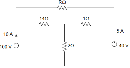
a) 10 Ω
b) 18 Ω
c) 24 Ω
d) 12 Ω
View Answer
Explanation: By KCL,
∴ \(\frac{V_P-40}{1} + \frac{V_P-100}{14} + \frac{V_P}{2}\) = 0
Or, 22 VP = 660
∴ VP = 30 V
Potential difference between node x and y = 60 V
∴ -I – 5 + \(\frac{40-30}{I}\) = 0
Or, I = 5 A
∴ R = \(\frac{60}{5}\)= 12 Ω.
2. In the circuit given below, the resistance between terminals A and B is 7Ω, between terminals B and C is 12Ω and between terminals C and A is 10Ω. The remaining one terminal in each case is assumed to be open. Then the value of RA and RB are _________
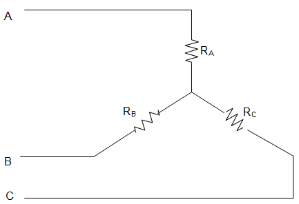
a) RA = 9 Ω and RB = 7 Ω
b) RA = 2.5 Ω and RB = 4.5 Ω
c) RA = 3 Ω and RB = 3 Ω
d) RA = 5 Ω and RB = 1 Ω
View Answer
Explanation: Given RA + RB = 7 with C open
RB + RC = 12 with A as open
RA + RC = 10 with B open
Then, RA + RB + RC = \(\frac{29}{2}\) = 14.5
Hence, RA = 2.5 Ω, RB = 4.5 Ω and RC = 7.5 Ω.
3. Currents I1, I2 and I3 meet at a junction in a circuit. All currents are marked as entering the node. If I1 = -6sin(ωt) mA and I2 = 8 cos(ωt) mA, the I3 is ________
a) 10 cos(ωt + 36.87) mA
b) 14 cos(ωt + 36.87) mA
c) -14 sin(ωt + 36.87) mA
d) -10 cos(ωt + 36.87) mA
View Answer
Explanation: Applying KCL, we get, I1 + I2 + I3 = 0
∴ -6 sin(ωt) + 8 cos(ωt) + I3 = 0
∴ I3 = 6 sin (ωt) – 8 cos (ωt)
= 10[sin (ωt).sin (36.86) – cos (ωt) cos (36.86)]
=-10[cos (ωt) cos (36.86) – sin (ωt) sin (36.86)]
= -10 cos (ωt + 36.86)
[As, cos (A+B) = cosA.cosB – sinA.sinB].
4. Viewed from the terminals A and B the circuit given below can be reduced to an equivalent circuit with a single voltage source in series with a resistor with ________
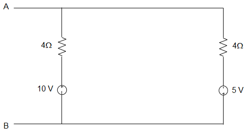
a) 5 V source in series with 10 Ω resistor
b) 1 V source in series with 2.4 Ω resistor
c) 15 V source in series with 2.4 Ω resistor
d) 1 V source in series with 10 Ω resistor
View Answer
Explanation: Applying Thevenin’s Theorem REQ = 6 || 4
= \(\frac{6 × 4}{6 + 4}\)
= \(\frac{24}{10}\) = 2.4 Ω
VAB = 10 – 6 × (\(\frac{15}{10}\)) = 1 V.
5. In the circuit given below, the voltage across the 2Ω resistor is ________
a) 3.41 V
b) -3.41 V
c) 3.8 V
d) -3.8 V
View Answer
Explanation: Applying KCL to node A, \(\frac{V_A-10}{10} + \frac{V_A}{20} + \frac{V_A}{7}\) = 0
Or, VA (0.1 + 0.05 + 0.143) = 1
Or, VA = 3.41 V
The voltage across the 2 Ω resistor due to 10 V source is V2 = \(\frac{V_A}{7} × 2\) = 0.97 V
V2Ω due to 20 V source, \(\frac{V_A}{10} + \frac{V_A}{20} + \frac{V_A-20}{7}\) = 0
Or, 0.1 VA + 0.05VA + 0.143VA = 2.86
∴ VA = \(\frac{2.86}{0.293}\) = 9.76 V
V2Ω = \(\frac{V_A-20}{7}\) × 2 = -2.92 V
The current in 2 Ω resistor = 2 × \(\frac{5}{5+8.67}\)
= \(\frac{10}{13.67}\) = 0.73 A
The voltage across the 2 Ω resistor = 0.73 × 2 = 1.46 V
V2Ω = 0.97 – 2.92 -1.46 = -3.41 V.
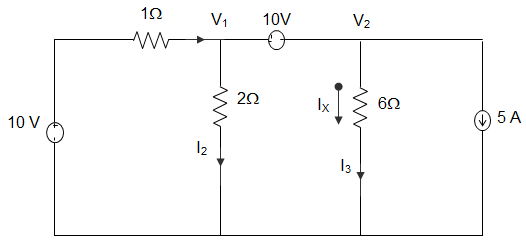
6. In the circuit given below, the value of IX using nodal analysis is _______
a) -2.5 A
b) 2.5 A
c) 5 A
d) -5 A
View Answer
Explanation: Applying KCL, we get, I1 + 5 = I2 + I3
∴ \(\frac{10 – V_1}{1} + 5 = \frac{V_1}{2} + \frac{V_2}{6}\)
∴ 30 – 3V1 + 15 = 3V1 + V2
∴ 6 V1 + V2 = 45
From voltage source, V2 – V1 = 10
Now, 7 V1 = 35, V1 = 5 V
And V2 = 15 V
∴ IX = \(\frac{V_2}{6} = \frac{15}{6}\) = 2.5 A.
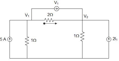
7. In the circuit given below, the values of V1 and V2 respectively are _________
a) 0 and 5V
b) 5 and 0 V
c) 5 and 5 V
d) 2.5 and 2.5 V
View Answer
Explanation: I1 = \(\frac{V_1-V_2}{2}\)
Applying KCL at node 1, 5 = \(\frac{V_1}{1} + \frac{V_1-V_2}{2} + V_1 \)
10 = 2V1 + V1 – V2 + 2V1
Or, 10 = 5V1 – V2
KCL at node 2, \(\frac{V_1-V_2}{2}\) + V1 + 2I1 = V2
∴ 1.5 V1 – V2 = 0
∴ V1 = V2 = 2.5 V.
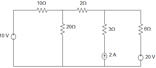
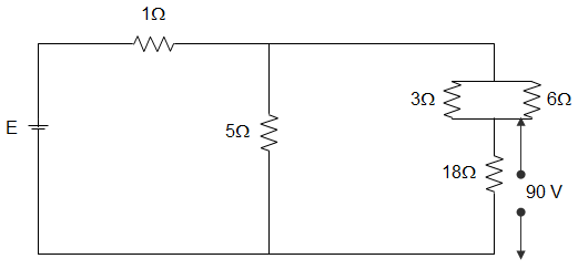
8. In the circuit given below, the voltage across the 18 Ω resistor is 90 V. The voltage across the combined circuit is _________
a) 125 V
b) 16 V
c) 24 V
d) 40 V
View Answer
Explanation: Current through the 18 Ω resistance = \(\frac{90}{18}\) = 5 A
Equivalent resistance of 3 Ω and 7 Ω banks = \(\frac{3 × 6}{3 + 6}\) = 2 Ω
Since, this 2 Ω resistance is in series with 18 Ω resistance, therefore total resistance = 18 + 2 = 20 Ω
This 20 Ω resistance is in parallel with 5 Ω resistance = \(\frac{5 × 20}{5 + 20}\) = 4 Ω
Hence, total resistance of the circuit = 1 + 4 = 5 Ω
Current through this branch = 5 A
∴ Voltage across dc= 5 × 20 = 100 V
Hence current through 5 Ω resistance = \(\frac{100}{5}\) = 20 A
∴ Total current = 20 + 5 = 25 A
Since, total resistance of the circuit is 5 Ω therefore, voltage E = 25 × 5 = 125 V.
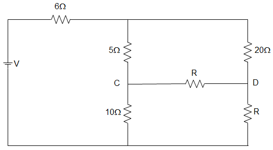
9. In the circuit given below, the value of R in the circuit, when the current is zero in the branch CD is _________
a) 10 Ω
b) 20 Ω
c) 30 Ω
d) 40 Ω
View Answer
Explanation: The current in the branch CD is zero if the potential difference in the branch CD is zero.
That is, VC = VD
Or, V10 = VC = VD = VA × \(\frac{10}{15}\)
VR = VA × \(\frac{R}{20+R} \)
And V10 = VR
∴ VA × \(\frac{10}{15}\) = VA × \(\frac{R}{R+20} \) ∴ R = 40 Ω.
10. Two capacitors of 0.5 μF and 1.5 μF capacitance are connected in parallel across a 110 V dc battery. The charges across the two capacitors after getting charged is ___________
a) 55 μC each
b) 275 μC each
c) 55 μC and 275 μC respectively
d) 275 μC and 55 μC respectively
View Answer
Explanation: Q1 = 0.5 x 10-6 x 110
= 55 μC.
Also, Q2 = 2.5 x 10-6 x 110
= 275 μC.
11. Consider a circuit having resistances 2 Ω and 2 Ω in series with an inductor of inductance 2 H. The circuit is excited by a voltage of 12 V. A switch S is placed across the first resistance. Battery has remained switched on for a long time. The current i(t) after switch is closed at t=0 is _____________
a) 6
b) 6 – 3e-t
c) 6 + 3e-t
d) 3 – 6e-t
View Answer
Explanation: From the figure, we can infer that,
I(t) = \(\frac{12}{12} \left(1 – \frac{2}{4} e^{-t}\right)\)
= 6 – 3e-t.
12. A resistance R is connected to a voltage source V having internal resistance RI. A voltmeter of resistance R2 is used to measure the voltage across R. The reading of the voltmeter is _____________
a) \(\frac{V_S R_1 R_2}{R_2 R_1 + R_1 R + RR_2}\)
b) \(\frac{V_s R}{R + R_s}\)
c) \(\frac{VR_1 R_2}{R_1 R_2 – R_1 R – RR_2}\)
d) \(\frac{V_S RR_2}{R_1 R_2 + R_1 R + RR_2}\)
View Answer
Explanation: Effective resistance of R and Rm is
Req = \(\frac{RR_m}{R + R_m}\)
Therefore the reading is \(\frac{V}{R_1 + \frac{R}{R + R_2}}\Big[\frac{RR_2}{R+R_2}\Big]\)
= \(\frac{V_S RR_2}{R_1 R_2 + R_1 R + RR_2}\).
13. When a lead acid battery is being charged, the specific gravity of the electrolyte will ___________
a) Decrease
b) Increase
c) Either Increase or Decrease
d) Neither Increase nor Decrease
View Answer
Explanation: We know that the specific gravity of electrolyte is highest when battery is fully charged and is lowest when discharged. So, the specific gravity of the electrolyte will increase when a lead acid battery is being charged.
14. A series RLC circuit has a resonant frequency of 550 Hz. The maximum voltage across C is likely to occur at a frequency of ___________
a) 1000 Hz
b) 2000 Hz
c) 1025 Hz
d) 500 Hz
View Answer
Explanation: We know that, maximum voltage across capacitance occurs at a frequency slightly less than resonant frequency.
Here, given that resonant frequency = 550 Hz.
So, out of the given options 500 is the lowest nearest integer to 550.
Hence, 975 Hz.
Sanfoundry Global Education & Learning Series – Network Theory.
To practice all areas of Network Theory, here is complete set of 1000+ Multiple Choice Questions and Answers.
If you find a mistake in question / option / answer, kindly take a screenshot and email to [email protected]
- Apply for Electronics & Communication Engineering Internship
- Check Electrical Engineering Books
- Check Network Theory Books
- Practice Electrical Engineering MCQs
- Apply for Electrical Engineering Internship
