This set of Aircraft Design Multiple Choice Questions & Answers (MCQs) focuses on “Aerodynamics – Lift”.
1. Following diagram represents ___________
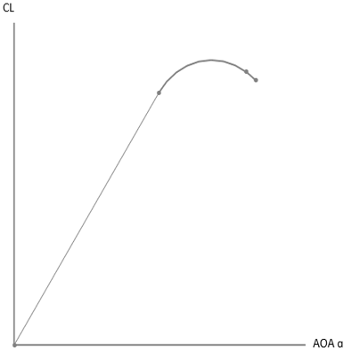
a) uncambered wing lift curve
b) cambered airfoil lift curve
c) cambered wing lift curve slope
d) uncambered airfoil
View Answer
Explanation: A typical diagram of lift curve is illustrated in above figure. The diagram is applicable to uncambered wing. Airfoil lift curve will be different from wing. Typically, lift coefficient of airfoil is greater than the wing.
2. Following diagram represents _______________
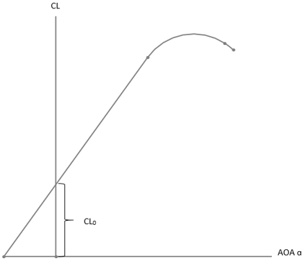
a) cambered wing lift curve
b) drag polar
c) thrust loading
d) power loading
View Answer
Explanation: A typical, lift curve is shown for Cambered airfoil. As shown in the diagram, camber wing with cambered airfoils will produce lift at small angle. Drag polar is used to provide information about drag characteristics. Thrust loading is defined as ratio of weight to thrust.
3. At same value of maximum lift AOA, lift coefficient of Cambered wing is _________
a) higher than uncambered wing
b) lower than uncambered wing
c) same as cambered airfoil always
d) not dependent on camber
View Answer
Explanation: Lift coefficient at maximum lift AOA for a cambered wing is higher than that of the uncambered wing. At maximum lift AOA, value of lift coefficient will be maximum as well. Further increase in angle will reduce the amount of lift generated by wing.
4. Following diagram represents _______
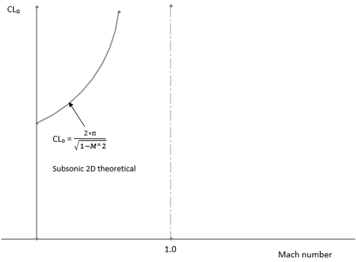
a) lift curve slope vs mach number
b) drag polar
c) thrust required minimum
d) wing loading chart
View Answer
Explanation: The above diagram is showing a typical variation between lift curve and Mach number. Drag polar is nothing but the drag variation with lift or angle of attack. It is used to estimate drag properties of airfoil and wing. Wing loading is defined as the ratio of weight to the reference area.
5. A 2D airfoil is operating at 0.6M. Find the approximate value of lift curve slope in per rad.
a) 7.85
b) 1.9
c) 2.3
d) 3.87
View Answer
Explanation: Given, mach number M = 0.6
2D lift curve slope = 2*π / (1-M2)0.5
= 2*π / (1-0.62)0.5 = 7.85 per rad.
6. A supersonic 2D airfoil has Mach number of 1.5. Find Lift curve slope of the airfoil.
a) 0.062 per degree
b) 0.062 per rad
c) 24 per degree
d) 12.56 per degree
View Answer
Explanation: Given, mach number M = 1.5
2D lift curve slope = 4 / (M2 – 1)0.5
= 4 / (1.52 – 1)0.5 = 3.57 per rad = 3.57/57.3 = 0.062 per degree.
7. If an airfoil is designed to provide lift curve slope as 7.8, then find airfoil efficiency. The actual lift curve slope of the airfoil is 7.4.
a) 94.87%
b) 45%
c) 15.6%
d) 98.7%
View Answer
Explanation: Airfoil efficiency = Actual lift curve slope / theoretical or designed lift curve slope
= 7.4/7.8 = 0.9487 = 94.87%.
8. A subsonic aircraft wing has aspect ratio of 8. Now we have been asked to provide winglet to this wing. Evaluate approximate value of effective aspect ratio of winglet is considered.
a) 9.6
b) 23
c) 32
d) 4.89
View Answer
Explanation: Approximate effective aspect ratio = 1.2*Wing aspect ratio
= 1.2*8 = 9.6.
9. A subsonic aircraft has unswept wing which has maximum lift coefficient of 1.4. Now, consider wing is provided sweep of 25° at quarter chord point. Now, determine the change in maximum lift coefficient due to the provision of sweep.
a) Maximum Lift coefficient will be reduced by 0.2580 amount
b) Increment by 1.245
c) Decreases by 0.0476 amount
d) Maximum lift coefficient will increase by 56%
View Answer
Explanation: Given, unswept maximum lift coefficient CL1 = 1.4
Now, sweep of 25° is provided at quarter chord point. Hence sweep angle at quarter chord s = 25°
Maximum lift coefficient CL2 = CL1*0.9*cos (a)
= 1.4*0.9*cos (25°) = 1.1419.
Now, change in maximum lift coefficient = CL2 – CL1 = 1.1419 – 1.4 = -0.2580.
Hence, by implementing the sweep of 25° maximum lift coefficient is reduced by 0.2508 unit.
10. Following diagram represents __________
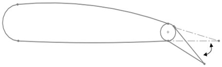
a) plain flap
b) aileron
c) rudder
d) spoiler
View Answer
Explanation: Flap is a high lift device. Flap is used to increase lift produced by wing during landing and takeoff. Aileron is used to bank the aircraft. Rudder provides yawing motion to the aircraft. Spoiler is used to provide additional drag during landing.
Sanfoundry Global Education & Learning Series – Aircraft Design.
To practice all areas of Aircraft Design, here is complete set of 1000+ Multiple Choice Questions and Answers.
If you find a mistake in question / option / answer, kindly take a screenshot and email to [email protected]
- Check Aircraft Design Books
- Check Aeronautical Engineering Books
- Practice Aerospace Engineering MCQs
- Apply for Aerospace Engineering Internship
- Practice Aeronautical Engineering MCQs
