This set of Aircraft Design Multiple Choice Questions & Answers (MCQs) focuses on “Gear-Retraction Geometry”.
1. Following diagram represents ______

a) in the wing gear retraction
b) cockpit
c) cargo containers
d) tail Podded
View Answer
Explanation: As shown in figure, a typical gear retraction geometry is shown. As shown in the figure, gear is retracted inside the wing. Hence, it is called in the wing retraction geometry. Cockpit is front section of an aircraft through where pilot controls the aircraft.
2. Following diagram represents ______

a) wing podded retraction
b) fuselage podded retraction
c) lift curve
d) tail plane retraction
View Answer
Explanation: A typical wing podded gear retraction is shown in the diagram. Fuselage Podded will not be retracted inside wing. Lift curve is used to represent relationship between lift and angle of attack. Lift curve is very important parameter.
3. Following diagram represents ______
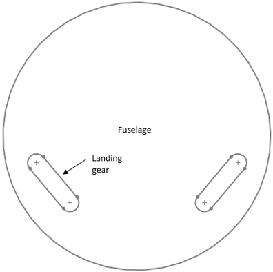
a) in the fuselage gear retraction
b) in wing retraction
c) retraction in cockpit
d) headroom
View Answer
Explanation: Typical gear retraction in the Fuselage is shown in the above diagram. It is similar to in the wing retraction geometry with difference being in the location of retraction. Here, gear will be retracted in the fuselage itself. Headroom is related to passenger cabin.
4. Following diagram represents ______
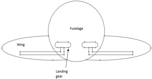
a) gear retraction geometry
b) in cockpit
c) gear load chart
d) drag polar
View Answer
Explanation: Landing gear retraction is one of the important factor of landing gear design. Typical gear retraction geometry is shown in the above diagram. As shown in the diagram undercarriage is retracted inside the wing fuselage junction.
5. Following diagram represents ______
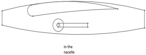
a) gear retraction geometry in the nacelle
b) gear retraction in fuselage
c) gear retraction in wing fuselage junction
d) gear retraction at wing tip
View Answer
Explanation: Typical, gear retraction inside the nacelle is shown in the diagram. This type of arrangement can be seen in early prop aircraft. Gear retraction in fuselage or wing fuselage junction are nearly similar to each other.
6. Following diagram represents ______
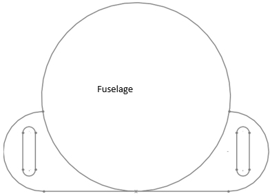
a) typical fuselage Podded retraction
b) tail tip podded
c) wingtip retraction
d) thrust required
View Answer
Explanation: Above diagram is representing the typical layout of fuselage Podded retraction geometry. Here, landing gear will be retracted inside the fuselage section of the aircraft. Thrust required will be based on operating conditions. At cruise, thrust required is equal to drag.
7. Pivot point is defined as?
a) The point at which the landing gear leg is attached to the aircraft
b) The point at which thrust forces is acting
c) The point with maximum lift to drag
d) CG of only quadric cycle gear
View Answer
Explanation: The point at which landing gear or undercarriage leg is attached to the aircraft is known as pivot point. This pivot point can be located anywhere along the normal bisector to the line joining the up and down wheel positions. Lift to drag will be maximum at thrust required minimum.
8. Drag brace is used to __________
a) withstand aerodynamic loads and breaking loads
b) reduce drag
c) lowers the weight of an aircraft
d) decrease the drag produced by gear only
View Answer
Explanation: Typical landing gear retraction arrangement includes a diagonal arm. This diagonal arm for nose wheel is called drag brace. Drag brace is used to withstand the breaking loads and aerodynamic loads as well.
9. Following diagram represents ___________
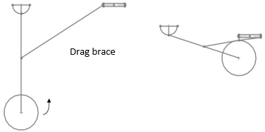
a) sliding pivot mechanism
b) lift augmentation
c) thrust augmentation
d) drag polar
View Answer
Explanation: The above figure is illustrating a typical sliding pivot mechanism. It is different from the typical four bar linkage system. Lift augmentation is used to increase lift. Thrust can be increased by thrust augmentation. Drag polar is graph showing relationship between drag and lift.
10. Which of the following is correct?
a) Sway brace is typically used for main landing gear
b) Lift is always same as weight
c) Lift opposes the aircraft forward motion
d) Drag is propulsive force produced by landing gear to accelerate an aircraft
View Answer
Explanation: Sway brace term is typically used for main landing gear. It is also used to withstand aerodynamic loads and breaking loads. They are used to provide lateral support for the gears. Aircraft forward motion is primarily opposed by drag. Lift is not always same as weight.
11. Following diagram represents _________
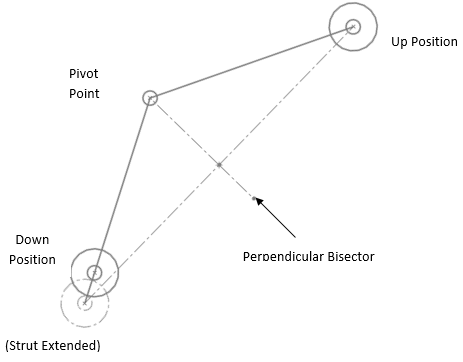
a) pivot point estimation
b) triangular curve mechanism
c) drag characteristics
d) lift estimation via drag polar
View Answer
Explanation: Above diagram is a simple schematic diagram illustrating the method to estimate the pivot point. Drag characteristics can be observed through numbers of graph for example, drag polar etc. Drag polar will be used to generate a typical drag property variation with respect to lift variation.
Sanfoundry Global Education & Learning Series – Aircraft Design.
To practice all areas of Aircraft Design, here is complete set of 1000+ Multiple Choice Questions and Answers.
If you find a mistake in question / option / answer, kindly take a screenshot and email to [email protected]
- Check Aircraft Design Books
- Check Aeronautical Engineering Books
- Practice Aerospace Engineering MCQs
- Apply for Aerospace Engineering Internship
- Check Aerospace Engineering Books
