This set of Aircraft Design Multiple Choice Questions & Answers (MCQs) focuses on “Configuration Layout – Structural Considerations”.
1. What is the load path?
a) Structural elements by virtue of which opposing forces are connected
b) Structural elements by virtue of which similar forces are connected
c) Structural elements by virtue of which opposite moments are linked
d) Lifting path
View Answer
Explanation: Load path is nothing but the elements by virtue of which opposing forces are connected. Typically, a good structural arrangement will have efficient load path. By providing appropriate load path, we can improve our design based on structural considerations.
2. We can minimize the weight of the structural member by _________
a) placing opposite forces near to each other
b) placing opposite forces away from each other
c) placing similar forces near to each other
d) placing only upward forces near to each other
View Answer
Explanation: To reduce the structural weight it is required that our design should have efficient load paths through which we can effectively connect opposing forces. For a typical aircraft, two common forces to be resolved are lift and force. Hence, by locating opposite forces near to each other we can improve structural considerations of our design.
3. Span-loading is defined as __________
a) distribution of weight along span as lift distribution
b) thrust loading
c) wing loading
d) inverse of power loading
View Answer
Explanation: Span-loading is the distribution of weight along span as lift is distributed. Thrust loading is the ratio of thrust and weight. Wing loading is weight per area. Power loading is weight of aircraft to the power produced.
4. To reduce weight of the structural member we can __________
a) provide shortest and straightest possible load paths
b) provide only straightest possible load paths
c) provide only shortest possible load paths
d) provide shortest and highly curved possible load paths
View Answer
Explanation: In general it is required to locate opposing forces at the same location. We can reducing weight by doing so. However, it is not possible for every scenario. Hence, we need to provide some path through which we can connect these forces. These paths are load paths and by providing shortest and straightest possible load path we can reduce the weight.
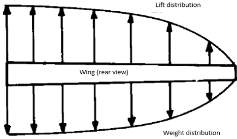
5. Following diagram represents __________

a) ideal span loading
b) ideal thrust loading
c) ideal wing loading
d) ideal power loading
View Answer
Explanation: Above figure is representing the distribution of lift and weight along the span. It is shown in figure that weight is distributed exactly same as lift along the span. This is ideal condition and termed as ideal span loading.
6. Longerons are used to oppose __________
a) bending
b) expansion only
c) contraction only
d) drag
View Answer
Explanation: Longerons are structural members of an aircraft. They are heavy and used to prevent the bending. Longerons are fewer in numbers and primarily opposes the loads which can result in the bending stress and can cause the bending of structure. Their placement should be considered while designing the aircraft.
7. To decrease the weight of a typical commercial fuselage, stringers should be _________
a) straight and uninterrupted
b) straight and curved
c) interrupted at every point
d) only straight
View Answer
Explanation: A typical transport fuselage will have more numbers of stringers attached to its structure. Stringers are short and light structural elements. They are distributed around fuselage circumference. Stringers should be straight and uninterrupted to minimize the weight as possible and as per our requirement.
8. Fuselage bending loads are carried by ___________
a) keelson
b) tail
c) nelson
d) ribs
View Answer
Explanation: Keelson is a large beam placed at fuselage bottom. Keelson is structural element through which bending loads are carried out. Tail is after section of the aircraft which has primary purpose to provide stability and control.
9. If possible, we should avoid using any structural cutout.
a) True
b) False
View Answer
Explanation: Typically, cutouts will increase the weight of the structure. A cutout provided at the wing carry through box in order to place landing gear or undercarriage will require larger cutout and will increase load as well. Hence, if possible then we should avoid it.
10. Following diagram represents ______

a) wing box carrythrough
b) ring frames
c) bending beams
d) strut braced
View Answer
Explanation: Wing box carry through arrangement is shown in above diagram. These arrangement is widely used in general aviation and transport aircrafts. Here, box is continued from wing through the fuselage as can be seen in the diagram.
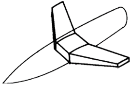
11. Following diagram represents ______

a) ring frames
b) bending beams
c) strut braced
d) hybrid strut braced
View Answer
Explanation: A typical ring frames arrangement is shown in above diagram. In this type of wing carry through, large and heavy bulkheads are used. These bulkheads are used to oppose the bending. This type is mostly used by modern fighters.
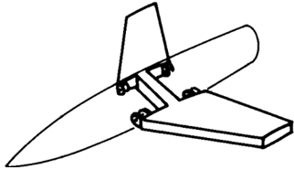
12. Following diagram represents ______

a) bending beams
b) ring frames
c) strut braced
d) hybrid strut braced
View Answer
Explanation: Bending beam arrangement is shown in above diagram. This type is combination of the wing box and ring frames wing carry through arrangement. Strut braced will rely upon strut and used in slower transport aircraft typically.
13. A wing has chord of 1m. Find the appropriate range of the front spar position from l.e.
a) 0.2m-0.3m
b) 0.9m-1.5m
c) 3.2
d) 1.2
View Answer
Explanation: Given chord c = 1m.
Typical range of front spar location = 20% to 30% of chord = 20% of 1 to 30% of 1 = 0.2*1 to 0.3*1 = 0.2m-0.3m.
14. A spar is located at 65% of MAC from leading edge. If spar is positioned in such way that distance between t.e. and spar is 2m then, estimate chord of wing.
a) 5.71m
b) 6.8
c) 4.4
d) 6.5
View Answer
Explanation: Given location of spar = 65% of MAC, distance from t.e. = 2m.
Spar is located at 65% of chord from l.e. hence, from t.e. location of spar = (100% – 65%) of chord = 1-0.65 = 0.35*chord.
From given, 0.35*chord = 2m
Chord = 2/0.35 = 5.71m.
15. A typical large airliner has outer diameter of 20in. find the approximate value of diameter for passenger compartment.
a) 12in
b) 34in
c) 20in
d) 24in
View Answer
Explanation: Given external diameter = 20in. Radius = 20/2 = 10in.
Approximate radius of passenger compartment = external radius – structural thickness
= 10-4 = 6in
Hence, diameter = 2*6 = 12in.
Sanfoundry Global Education & Learning Series – Aircraft Design.
To practice all areas of Aircraft Design, here is complete set of 1000+ Multiple Choice Questions and Answers.
If you find a mistake in question / option / answer, kindly take a screenshot and email to [email protected]
- Apply for Aerospace Engineering Internship
- Check Aerospace Engineering Books
- Practice Aeronautical Engineering MCQs
- Practice Aerospace Engineering MCQs
- Check Aircraft Design Books
