This set of Aircraft Design Multiple Choice Questions & Answers (MCQs) focuses on “Propulsion – Jet-Engine Integration-1”.
1. What do you mean by scale factor in terms of rubber engine?
a) ratio of thrust required by rubber engine to the actual thrust from selected existing engine
b) Lift to drag ratio
c) Thrust coefficient to drag coefficient
d) Thrust required to thrust available
View Answer
Explanation: For a typical rubber engine, scale factor is defined as ratio of thrust required by rubber engine to the actual thrust from selected existing engine. Scale factor can vary based on our requirements. Lift to drag ratio is primarily concern of aerodynamics of aircraft.
2. Which of the following is correct?
a) Length L = Lactual*(SF) 0.4
b) Length L = Lactual / (SF) 0.4
c) Length L = Lactual*(SF) 2
d) Length L = 2*Lactual
View Answer
Explanation: If our chosen existing engine has length of Length of Lactual then, the length of rubber engine is given by, Length L = Lactual*(SF)0.4. SF stands for scale factor.
3. A Turbofan engine is to be scale in order to have our desired engine characteristics. If length of the existing engine selected is 2.5 unit and required scale factor is 0.8 then, evaluate approximate length of our engine.
a) 2.28 unit
b) 5.6 unit
c) 10 unit
d) 15 unit
View Answer
Explanation: Given, actual length Lactual = 2.5unit, S.F. = 0.8
Approximate length is given by,
Length L = Lactual*(SF) 0.4
Length L = 2.5*(0.8) 0.4 = 2.28 unit.
4. Diameter of rubber engine is 94 inch and required scale factor is 0.7 then, what will be the actual diameter of selected engine?
a) 112.35 in
b) 150 in
c) 200 in
d) 50 in
View Answer
Explanation: Given, diameter d = 94 inch, S.F. = 0.7
Now, actual diameter is given by,
Actual diameter D = d / (SF)0.5 = 94 / (2.7)0.5 = 112.35in.
5. Evaluate required scale factor if ratio of weight of the rubber engine and the actual selected engine is 0.8.
a) 0.8164
b) 0.012
c) 6.2
d) 1
View Answer
Explanation: Given, ratio of rubber engine weight (w) and actual engine weight (W) = 0.8
Now, weight of the rubber engine is given by, w = W * SF1.1
Hence, SF1.1 = w/W = 0.8
1.1*ln (SF) = ln0.8 = -0.223
Hence, ln (SF) = -0.223/1.1 = -0.2028
Hence, SF = e-0.2028 = 0.8164.
6. Subsonic non after burning engine needs to be design based on following data. Take off trust is 15000 N and bypass ratio is 1.2. Find the weight of this engine. Consider first order statistical jet engine model.
a) 3123 unit
b) 325 unit
c) 445.5 unit
d) 560.59 unit
View Answer
Explanation: Given, Thrust T = 15000N, BPR = 1.2
Now, weight is given by, W = 0.084 * (T1.1)* e (-0.045*BPR).
W = 0.084 * (150001.1) * e (-0.045*1.2) = 0.084*39237.4147*0.9474 = 3123 unit.
7. Based on first order statistical jet engine model, we have been given a task to design a subsonic non afterburning engine which is operating at maximum Mach number of 0.7. Evaluate the approximate length required to build this engine. Given thrust at takeoff is 9600 unit.
a) 81 unit
b) 10 unit
c) 20 unit
d) 22 unit
View Answer
Explanation: Given, Thrust = 9600unit, Mach number M = 0.7
Length L = 2.22*T0.4*M0.2 = 2.22*96000.4*0.70.2 = 2.22*39.165*0.9311 = 80.95 ∼ 81 unit.
8. Engine which can be estimated through statistical jet engine model has bypass ratio of 1.2 and maximum thrust at takeoff is 8000 Newton then what should be the design diameter for this engine. Consider a subsonic non after burning engine.
a) 36.87 unit
b) 6.19 unit
c) 7.2 unit
d) 58.93 unit
View Answer
Explanation: Given, Thrust = 8000unit, BPR = 1.2
Diameter d is given by, d = 0.393 * (T0.5) * e (0.04 * BPR) = 0.393 * (8000)0.5 * e (0.04 * 1.2)
= 0.393*89.442*1.049 = 36.87 unit.
9. If bypass ratio of subsonic non afterburning engine is 1.5 then, what will be the value of maximum thrust specific fuel consumption.
a) 0.556
b) 0.12
c) 0.0789
d) 0.092
View Answer
Explanation: Given, BPR =1.5
Maximum thrust SFC = 0.67*e(-0.12*BPR) = 0.67* e(-0.12*1.5) = 0.556.
10. Subsonic non afterburning engine has takeoff thrust of 8000 Newton and is operating with BPR of 1.2 then, what will be the approximate value of thrust at cruise.
a) 2001.5 unit
b) 1001.5 unit
c) 500 unit
d) 100 unit
View Answer
Explanation: Given, Thrust T1 = 8000N, BPR = 1.2
Now, thrust at cruise T = 0.60 * T10.9 * e (0.02*BPR) = 0.60 * (8000)0.9 * e (0.02*1.2) = 0.60*3256.724*1.024 = 2001.49 = 2001.5 unit.
11. Inlet location will not affect engine performance.
a) True
b) False
View Answer
Explanation: Location of an inlet is very important factor in one of the crucial factor affecting engine performance. Inlet location is affected by Wing wake, vortex etc. Hence, as a result of wake and vortex engine can stall. Therefore, inlet location should be adequate.
12. Which of the following is an advantage of nose inlet?
a) Clean airflow
b) Unclean airflow
c) Very long internal duct
d) Swirled flow always
View Answer
Explanation: The nose inlet offers clean air flow. It was used in some fighters such as Mig 21. This type of inlet requires long internal duct which is one of the disadvantages of nose inlet. They are typically located at the nose section of an aircraft.
13. Chin inlet sufferers from _____________
a) foreign object ingestion problem
b) shorter duct length
c) duct length is shorter than the nose inlet
d) typically good at high AOA
View Answer
Explanation: Chin inlet is good at operating higher AOA. They offers advantages similar to nose but required duct length is shorter. One of the disadvantage of this type is foreign object ingestion. This good affect the performance of engine as well.
14. Following diagram represents _____________
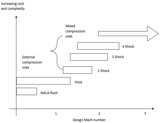
a) inlet applicability
b) outlet geometry
c) exhaust section
d) empennage
View Answer
Explanation: Typical inlet application limits based on Mach number is shown in the diagram. Above diagram is illustrating the selection criteria. This criteria is presented for different types of inlets based upon designed Mach values.
15. Large cowl lip radius will produce ____________
a) shock separated flow outside of the inlet
b) shock attached flow
c) high lifting tendency always
d)expansion fan
View Answer
Explanation: Engine performance is influenced by cowl lip radius. A large cowl lip radius will produce shock separated flow on the outside of an inlet. Large cowl lip will reduce distortions. This is very helpful at higher AOA.
Sanfoundry Global Education & Learning Series – Aircraft Design.
To practice all areas of Aircraft Design, here is complete set of 1000+ Multiple Choice Questions and Answers.
If you find a mistake in question / option / answer, kindly take a screenshot and email to [email protected]
- Practice Aerospace Engineering MCQs
- Apply for Aerospace Engineering Internship
- Check Aircraft Design Books
- Check Aeronautical Engineering Books
- Practice Aeronautical Engineering MCQs
