This set of Aircraft Design Multiple Choice Questions & Answers (MCQs) focuses on “Propulsion – Jet-Engine Integration-3”.
1. Following diagram represents ______________
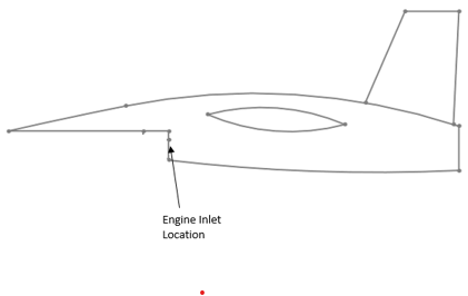
a) chin inlet
b) armpit inlet
c) wing tip inlet
d) tail tip inlet
View Answer
Explanation: A typical chin inlet arrangement is shown in the diagram. When inlet is located at tip of the wing then, it is termed as wing tip inlet. Chin inlet are similar to that of the nose inlets.
2. Following diagram represents ________________
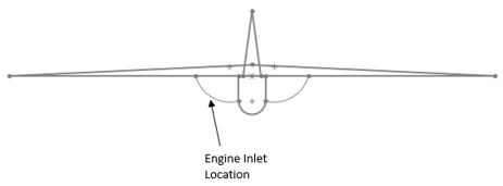
a) armpit inlet
b) wingtip inlet
c) lift curve
d) tail section
View Answer
Explanation: The above diagram is representing the typical armpit inlet location. This type of inlet is risky. This can be used to have short internal duct. Lift curve is curve representing lift variations.
3. Following diagram represents _______________
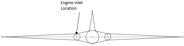
a) wing root inlet
b) armpit inlet
c) chin inlet
d) nose inlet
View Answer
Explanation: A typical wing root inlet can be seen in the above diagram. Nose inlet is located at nose section of the aircraft which can offer clearer airflow. Chin is similar to nose inlet with some fundamental modification. Armpit inlet location is considered to be risky.
4. Following diagram represents _________________

a) typical Podded engine
b) buried engine
c) nose buried engine location
d) side buried engine location
View Answer
Explanation: A typical Podded engine configuration is shown in the above diagram. Buried engines are located inside aircraft body itself. Nose buried engine and side buried engine are typical example of buried engine arrangements.
5. Following diagram represents ______________
a) tail podded engine
b) wing root buried engine
c) wingtip podded engine
d) wingtip buried engine
View Answer
Explanation: As shown in figure, typical tail podded engine is shown. As the name suggests this engine is located at empennage section of the aircraft. Wingtip is located at the tips of wing.
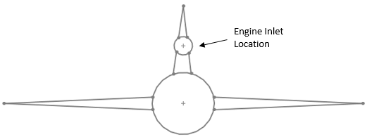
6. Which of the following is not an inlet location?
a) Side inlet location of buried engine
b) Tail root location
c) Lofting
d) Chin buried engine
View Answer
Explanation: Here, typical side inlet location of buried engine is shown. Tail root engine is located at root section of the tail. Lofting is mathematical modelling of aircraft components. It is an important step in aircraft design. Chin buried is similar to that of the nose inlet section. Chin inlet suffers from various drawbacks such as ingestion of foreign objects etc.
7. Find the diameter ratio of an engine which has mach number of 0.7. Consider isentropic flow.
a) 1.045
b) 2.045
c) 3.45
d) 5.64
View Answer
Explanation: Given, Mach number M = 0.7
Now, for Mach number 0.7 area ratio is 1.094.
Now, diameter ratio is given by,
Diameter ratio = (area ratio)0.5 = 1.0940.5 = 1.045.
8. Which of the following is an incorrect example for BL diverter?
a) Step diverter
b) Boundary layer bypass duct
c) Boundary layer suction
d) Flap
View Answer
Explanation: Boundary layer diverter is used to divert the boundary layer formed typically on the body. Step diverter, BL bypass duct and BL suction are some of the techniques used for this purpose. Flap is an example of high lift device.
9. Which of the following is an example of boundary layer diverter?
a) Boundary layer bypass duct
b) Fuselage fineness ratio
c) Thrust loading
d) Power loading curve
View Answer
Explanation: A boundary layer bypass duct or simply a separate inlet duct is one of example of boundary layer diverter. Fuselage fineness ratio is defined as ratio of fuselage length to the maximum diameter. Thrust loading is ratio of Thrust to weight. Power loading ratio of weight and power.
10. Which of the following will use suction to divert the boundary layer?
a) Boundary layer suction
b) Step diverter
c) Thrust loading
d) Power loading curve
View Answer
Explanation: Boundary layer suction is one of the type of the boundary layer diverter. Here, the boundary layer air is removed with the help of suction. It doesn’t benefit from the ram impact. Power loading is related to propulsion system performance.
11. Typical fighter is designed to operate at high angle of attack. Estimate the range of required boundary layer diverter thickness if fuselage length in front of the inlet is 10 unit.
a) 0.1 unit to 0.3 unit
b) 0.01 unit to 0.09 unit
c) 0.8 unit
d) 2.34 to 3.24 unit
View Answer
Explanation: Given, length l = 10 unit.
Typical boundary layer diverter thickness = 1% to 3% of length
= 1% of (10) to 3% of (10)
= 0.1 unit to 0.3 unit.
Sanfoundry Global Education & Learning Series – Aircraft Design.
To practice all areas of Aircraft Design, here is complete set of 1000+ Multiple Choice Questions and Answers.
If you find a mistake in question / option / answer, kindly take a screenshot and email to [email protected]
- Check Aircraft Design Books
- Practice Aeronautical Engineering MCQs
- Practice Aerospace Engineering MCQs
- Check Aerospace Engineering Books
- Check Aeronautical Engineering Books
