This set of Aircraft Design Multiple Choice Questions & Answers (MCQs) focuses on “Landing Gear Arrangements”.
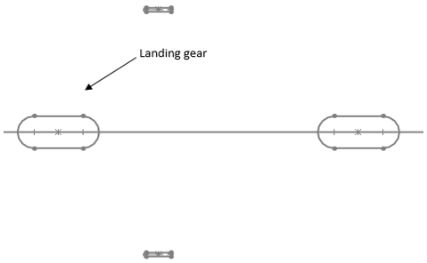
1. Following diagram represents ____________
a) bicycle
b) tricycle
c) tail dragger
d) quadruple
View Answer
Explanation: Typical bicycle landing gear arrangement is shown in the above diagram. As shown in the diagram, bicycle arrangement has 2 main landing gear and small outrigger wheels. It requires flat attitude for operation.
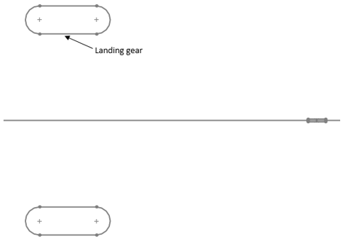
2. Following diagram represents _________
a) tail dragger
b) bicycle
c) tricycle
d) single main
View Answer
Explanation: Above diagram is representing a typical tail dragger landing gear arrangement. As shown in the diagram, tail dragger configuration has two main gears located ahead of cg. It also includes an auxiliary wheel at tail as shown in the diagram.
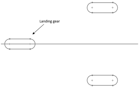
3. Following diagram represents _________
a) tricycle
b) bicycle
c) quadric cycle
d) tail pusher
View Answer
Explanation: Typical tricycle landing gear arrangement is shown in the above diagram. As shown in the diagram, two main landing gears are located after the c.g. It has an auxiliary third wheel which is placed forward of the centre of gravity.
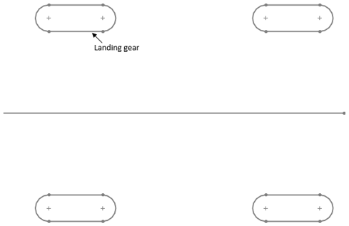
4. Following diagram represents ________
a) quadricycle
b) tail pusher
c) tail dragger
d) bicycle
View Answer
Explanation: Typical quadricycle landing gear arrangement is shown in the above diagram. As shown in the diagram, quadricycle landing gear arrangement has 4 landing gears. It is similar to bicycle but wheels are at sides of the fuselage.
5. Following diagram represents _________
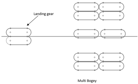
a) multi bogey
b) pusher prop
c) wing
d) bicycle
View Answer
Explanation: Above diagram is illustrating a typical multi- bogey landing gear arrangement. As shown in the diagram, multi bogey arrangement has more than 4 wheels to support higher impact loads and to carry heavy structure. Pusher prop is type of engine propulsion system.
6. Following diagram represents _________
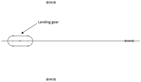
a) single main landing gear arrangement
b) wing lofting
c) empennage section
d) thrust loading chart
View Answer
Explanation: Above diagram is showing typical single main landing gear arrangement. Lofting is used to generate overall wing shape via conic lofting method. Empennage is tail portion of the aircraft. Thrust loading is defined as thrust to weight ratio.
7. Typically, an aircraft weighing lower than 50000 lb will adopt __________
a) single main gear
b) bicycle
c) tail dragger
d) tricycle
View Answer
Explanation: Given, weight W = 50000 lb. If weight w < 50000 lb then, the single main landing gear arrangement is used. Other arrangements are used if weight w is > 50000 lb.
8. What is the following is correct?
a) Quadricycle landing gear arrangement requires Flat takeoff attitude
b) Lift is always same as weight
c) Drag is always higher than weight
d) Thrust loading is weight to lift ratio
View Answer
Explanation: Quadricycle landing gear arrangement requires flat attitude for takeoff and landing. It is similar to bicycle arrangement. Lift is not always same as weight. Thrust loading is ratio of thrust to weight.
9. What is the location of main wheel in tricycle gear?
a) After CG of the aircraft
b) At CG
c) Before CG
d) At nose
View Answer
Explanation: Main wheel is located after the cg of the aircraft in typical tricycle landing gear arrangement. This arrangement is stable. An auxiliary wheel is located ahead of cg of the aircraft. It can be used for large crab angle as well.
10. Which of the following is disadvantage of tail dragger?
a) Inherent unstable
b) Most stable
c) Inherent stable
d) It has 4 wheels to support the aircraft
View Answer
Explanation: Tail dragger arrangement consists total of 3 wheels: 2 main and 1 auxiliary. Tail dragger arrangement is inherently Unstable. Tail dragger arrangement provides more propeller clearance and it is lighter in weight.
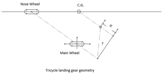
11. The term marked by ‘?’ in the following diagram is called __________
a) Overturn angle
b) Overnose angle
c) Grazing angle
d) AOA
View Answer
Explanation: The term marked is called overturn angle. It is measure of the tendency to overturn during taxied around sharp corner. For typical aircrafts this should not be more than 63°. AOA is angle between relative freestream velocity and chord.
12. What is tipback angle?
a) Maximum attitude of an aircraft with tail touching the ground with struts fully extended
b) Wing loading divided by span
c) Lift to drag ratio
d) Maximum altitude of an aircraft
View Answer
Explanation: Tipback angle is defined as Maximum attitude of an aircraft with tail touching the ground and the struts are completely extended. Wing loading is the ratio of weight and reference area. Lift to drag ratio is called aerodynamic efficiency.
13. An aircraft is supported by bicycle landing gear arrangement. If wheel base is 10 unit then, scale location of CG.
a) 5 unit aft from front wheel
b) 10 unit
c) 20 unit from front wheel
d) 25 unit from back wheel
View Answer
Explanation: Typically, for bicycle landing gear CG is aft of the midpoint between two wheels measured from front wheel.
Hence, Location of CG = distance/2 = 10/2 = 5 unit aft from front wheel.
14. Which of the following is correct?
a) Landing gear is also termed as undercarriage
b) Tail dragger arrangement is most stable
c) Lift coefficient is same as weight always
d) Lift to thrust is called thrust loading
View Answer
Explanation: Landing gear is also called undercarriage. Tail dragger arrangement is inherently Unstable. Lift coefficient cannot be same as weight always. Lift to drag ratio is called aerodynamic efficiency and very important parameter for aerodynamic consideration.
15. We should always use tail dragger arrangement for every aircraft.
a) True
b) False
View Answer
Explanation: Tail dragger arrangement was most widely used during first 40 to 50 years of aviation. Nowadays, this arrangement is limited to general aviation aircraft. This arrangement is inherently Unstable but are lighter in weight and provides more prop clearance.
Sanfoundry Global Education & Learning Series – Aircraft Design.
To practice all areas of Aircraft Design, here is complete set of 1000+ Multiple Choice Questions and Answers.
If you find a mistake in question / option / answer, kindly take a screenshot and email to [email protected]
- Apply for Aerospace Engineering Internship
- Check Aircraft Design Books
- Practice Aerospace Engineering MCQs
- Check Aerospace Engineering Books
- Check Aeronautical Engineering Books
