This set of Aircraft Design Multiple Choice Questions & Answers (MCQs) focuses on “Propulsion – Installed-Thrust Methodology”.
1. The actual available thrust used in performance calculations is termed as __________
a) installed net propulsive force
b) lift to drag ratio
c) installed weight to reference area
d) gross lift and weight
View Answer
Explanation: The actual available thrust used in performance calculations is termed as installed net propulsive force. Lift to drag ratio is called the aircraft Aerodynamic efficiency. It is primarily considered for Aerodynamic design. Weight to area is called wing loading.
2. Fudge factor is used to obtain ______________
a) manufacturer’s uninstalled engine thrust
b) thrust loading and wing loading
c) lofting
d) lift to drag ratio
View Answer
Explanation: Manufacturer’s Uninstalled engine Thrust can be obtained by using fudge factor or by using cycle analysis and/or testing. Thrust loading is defined as the ratio of the aircraft thrust to weight. Lofting is mathematical modelling of skin and it is one of the important factor for designing an aircraft.
3. What do you mean by installed engine thrust?
a) Actual thrust produced by an engine when installed
b) Actual thrust when not installed
c) Lifting property
d) Installed wing lift
View Answer
Explanation: The Actual thrust produced by an engine when installed in the Aircraft can be termed as installed engine thrust. To obtain install thrust we need to correct the thrust for actual inlet pressure recovery and nozzle performance. We also required to consider Thrust losses.
4. Following diagram represents __________
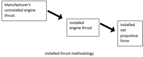
a) installed thrust methodology
b) uninstalled lift
c) lift to drag ratio determination
d) aerodynamic efficiency methodology
View Answer
Explanation: A typical installed thrust methodology is shown in the diagram. As shown in the diagram a typical Thrust methodology consists of 3 different processes. Each process has its own significance and is based on some assumptions as well. This can be seen in the diagram. Aerodynamic efficiency is determined by using lift and drag.
5. The installed net propulsive force is defined as _________
a) installed engine thrust minus the drag due to inlet, nozzle and throttle dependent trim drag
b) uninstalled thrust plus drag due to inlet and nozzle
c) installed lift by drag
d) installer wing loading
View Answer
Explanation: The installed net propulsive force is defined as installed engine thrust minus the drag due to inlet, nozzle and throttle dependent trim drag. This thrust value can be used to determine aircrew performance. Wing loading is defined as the ratio of weight of the aircraft to the reference area.
6. A manufacturer’s uninstalled engine is required to operate at 1.8M. Find the reference pressure recovery based on military standard.
a) 94.45%
b) 12.56%
c) 45.97%
d) 100%
View Answer
Explanation: Reference pressure recovery is defined as,
Reference pressure recovery = 1 – 0.075(M – 1)1.35
= 1 – 0.075(1.8 – 1)1.35 = 0.9445 = 94.45%.
7. Following diagram represents _________
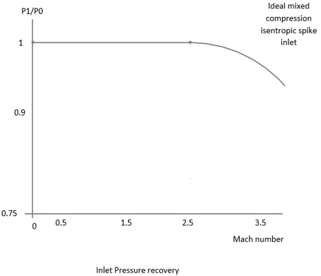
a) inlet pressure recovery concept
b) lift curve
c) inlet geometry
d) drag polar
View Answer
Explanation: A typical inlet pressure recovery concept is represented in the diagram. Lift curve is used to elaborate relationship between lift and angle of attack. Inlet geometry is the actual shape of an inlet for example ramp inlet, pitot inlet etc. Drag polar is graphical representation of drag characteristics.
8. A subsonic flight has actual inlet pressure recovery of 0.975. Estimate the thrust loss by this subsonic engine.
a) 3.37%
b) 56%
c) 2.5%
d) 11.22%
View Answer
Explanation: Given, subsonic Aircraft, actual inlet pressure recovery = 0.975.
Thrust loss can be approximated as follows,
% Thrust loss = C*(reference pressure recovery – actual inlet pressure recovery)*100
Since, C is not given we will consider it as 1.35. 1.35 is a typical value of C for subsonic aircraft.
Hence,
% Thrust loss = 1.35*(1-.975)*100 = 3.37%.
9. Engine manufacturer has provided the reference value of inlet pressure recovery as 0.94. If actual pressure recovery is found to be 0.91 then, find the thrust loss. Consider C of 1.25.
a) 0.0375
b) 0.123
c) 0.0865
d) 0.568
View Answer
Explanation: Given, actual inlet pressure recovery p1 = 0.91, reference inlet pressure recovery p = 0.94 and ram recovery Correction factor C=1.25
Now, thrust loss = C*(p-p1)
= 1.25*(0.94-0.91) = 0.0375.
10. A supersonic aircraft is designed to operate at 2.0M if thrust loss is required to be less than 2% then determine the reference value of inlet pressure recovery. Given ram recovery Correction factor C is 1.2.
a) 95%
b) 99
c) 102
d) 70
View Answer
Explanation: Reference pressure recovery = (Thrust loss/C) + actual pressure recovery
= 0.02/1.2 + 0.93
= 0.016+0.93 = 0.95 = 0.95*100% = 95%.
11. An engine has mass flow of 16 unit and bleed mass flow of 0.32 unit. Find the thrust loss due to the bleed air.
a) 4%
b) 6.98%
c) 100.78%
d) 21%
View Answer
Explanation: Since, bleed correction factor is not mentioned, we will consider it as 2. Hence, C = 2.
% Thrust loss = C*(bleed mass flow/engine mass flow)*100
= 2*(0.32/16)*100 = 4%.
12. If manufacturer’s thrust loss requirement is 3% and engine has mass flow of 20 unit then, determine how much bleed mass flow can be used?
a) 0.3 unit
b) 0.4 unit
c) 0.8 unit
d) 0.9835 unit
View Answer
Explanation: Bleed correction factor C can be approximated as 2 when it is not mentioned in the question.
Bleed mass flow = Thrust loss*Engine mass flow / C = 0.03*20/2 = 0.3 unit.
13. Which of the following is correct?
a) Drag due to air spilled before entering into the inlet is called additive drag
b) Lift is always equal to drag
c) Thrust loading is same as wing loading
d) Drag and lift are always unity
View Answer
Explanation: Additive drag is drag produced due to air spilled before entering into the inlet. Lift is not always equal to drag of the body. Thrust loading and wing loading both are two different terms and their physical significance is also different. It is not necessarily that drag and lift will be always unity.
14. Following diagram represents __________
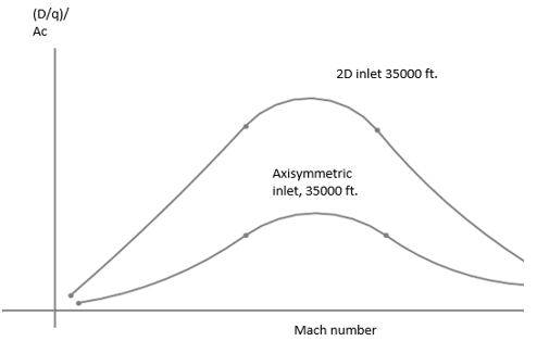
a) typical inlet drag trends
b) reynolds number
c) drag polar
d) lift coefficient curve
View Answer
Explanation: Above diagram is showing a typical variation in inlet drag with Mach number. Reynolds number is as non-dimensional quantity. We can use Reynold’s number to get understanding of the fluid flow and more.
15. Nozzle drag varies with _________
a) position of nozzle, flight conditions, etc
b) only nozzle flight conduit
c) only with nozzle type
d) only with nozzle pressure at combustion chamber
View Answer
Explanation: Drag is an opposite forces which resists the forward motion of the aircraft. Nozzle drag depends upon number of the factor such as: Location of nozzle, flight conditions etc. Nozzle is an important device to generate enough velocity and Thrust by expanding the flow.
Sanfoundry Global Education & Learning Series – Aircraft Design.
To practice all areas of Aircraft Design, here is complete set of 1000+ Multiple Choice Questions and Answers.
If you find a mistake in question / option / answer, kindly take a screenshot and email to [email protected]
- Practice Aerospace Engineering MCQs
- Apply for Aerospace Engineering Internship
- Check Aeronautical Engineering Books
- Practice Aeronautical Engineering MCQs
- Check Aerospace Engineering Books
