This set of Mechanical Metallurgy Multiple Choice Questions & Answers (MCQs) focuses on “Fracture Mechanics – Stress Intensity Factor”.
1. The value of the geometric parameter for a plate of width w loaded in tension with the centrally loaded crack of the length 2a __________
a) [w/2π tan(πa/w)]1/2
b) [wtan(πa/w)]1/2
c) [w/2π tan(πa/w)]
d) [w/2π]
View Answer
Explanation: The geometric parameter value depends upon the shape and size of the crack length. In general, it is denoted by α, and for the plate of width w loaded in the tension, it is given as the
-> [w/2π tan(πa/w)]1/2.
2. In determining the fracture toughness, the Mode-I is defined as _____________
a) crack opening mode
b) forward shear mode
c) parallel shear mode
d) perpendicular shear mode
View Answer
Explanation: Mode-I is referred to as the crack opening mode in which the tensile stress is applied in the y-direction normal to the face of the crack. This is the usual mode of determining the fracture toughness.
3. In determining the fracture toughness, the Mode-II is defined as the _____________
a) crack opening mode
b) forward shear mode
c) parallel shear mode
d) perpendicular shear mode
View Answer
Explanation: Mode-II is referred to as the forward shearing mode in which the shear stress is applied normal to the leading edges of the crack but in the plane of the crack.
4. In determining the fracture toughness, the Mode-III is defined as the _____________
a) crack opening mode
b) forward shear mode
c) parallel shear mode
d) perpendicular shear mode
View Answer
Explanation: Mode-III is also referred to as the parallel shear mode. In this, the shearing stresses are applied parallel to the leading edge of the crack.
5. The following diagram shows crack deformation mode. Which mode of fracture is shown?
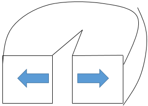
a) Mode-I
b) Mode-II
c) Mode-III
d) Need more information
View Answer
Explanation: The given diagram shows Mode-I, which is crack opening mode. In this, the tensile stress is applied in the y-direction normal to the face of the crack.
6. The following diagram shows crack deformation mode. Which mode of fracture is shown?
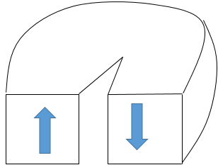
a) Mode-I
b) Mode-II
c) Mode-III
d) Need more information
View Answer
Explanation: This given diagram show the mode-III of crack deformation. In this, the shearing stresses is applied parallel to the leading edge of the crack.
7. In the Crack opening Mode-I, the extreme case is the thin plate which shows the condition of ____________
a) plane stress
b) plane strain
c) uniaxial stress
d) uniaxial strain
View Answer
Explanation: There are two extreme cases of crack opening mode-I in which the thin plate shows the condition of plane stress.
8. In the Crack Opening Mode-I, the extreme case is the thick plate which shows the condition of ____________
a) plane stress
b) plane strain
c) uniaxial stress
d) uniaxial strain
View Answer
Explanation: The other extreme case of the crack opening mode is that in which the thick plate shows the condition of plane strain. The condition of plane strain is much more severe than the condition of plane stress.
9. The plane-strain value of critical stress intensity factor KIc is independent of the specimen thickness and describes the fracture toughness of the durable material. Here, in the KIc the I represents _____
a) mode of fracture
b) number of stress state
c) number of strain state
d) the magnitude of fracture toughness
View Answer
Explanation: In KIc the I indicates the mode of fracture, and in this case, it shows the crack opening mode or tearing mode.
10. In the case of plane stress, the relationship between the fracture toughness and crack extension force is given as _______ (where K is the fracture toughness, δ is the crack extension force, and E is the young’s modulus).
a) K=δE
b) K2=δE
c) K=(δE)2
d) K=δ/E
View Answer
Explanation: For the real calculation, the crack extension force and fracture toughness parameters are much more useful in the calculation than other parameters. The relationship between them is given as;
=> K2=δE.
11. In the case of plane strain, the relationship between the fracture toughness and crack extension force is given as _______ (where K is the fracture toughness, δ is the crack extension force, ν is the poison’s ratio, and E is the young’s modulus).
a) K=δE
b) K2=δE/(1-ν2)
c) K=(δE)/ν
d) K=δ/E
View Answer
Explanation: In the case of the plane strain, the relationship between the fracture toughness and young’s modulus is given by :
-> K2=δE/(1-ν2).
Sanfoundry Global Education & Learning Series – Mechanical Metallurgy.
To practice all areas of Mechanical Metallurgy, here is complete set of 1000+ Multiple Choice Questions and Answers.
If you find a mistake in question / option / answer, kindly take a screenshot and email to [email protected]
- Practice Metallurgical Engineering MCQs
- Check Metallurgical Engineering Books
- Apply for Metallurgical Engineering Internship
- Check Mechanical Metallurgy Books
