This set of Analog Circuits Multiple Choice Questions & Answers (MCQs) focuses on “BJT Configuration”.
1. For a BJT, for common base configuration the input characteristics are represented by a plot between which of the following parameters?
a) VBE and IE
b) VBE and IB
c) VCE and IC
d) VCC and IC
View Answer
Explanation: The input signal is applied between the base and the emitter terminals. Input current flowing is the base current and hence characteristics are represented by a plot between VBE and IB.
2. For a BJT, for common base configuration the output characteristics are represented by a plot between which of the following parameters?
a) VBE and IB
b) VCE and IC
c) VCB and IC
d) VCE and IB
View Answer
Explanation: The input signal is applied between the collector and the emitter terminals. Input current flowing is the collector current and hence characteristics are represented by a plot between VCE and IC.
3. In a BJT, if the collector-base junction is reverse-biased and the base-emitter junction is forward-biased, which region is the BJT operating in?
a) Saturation region
b) Active region
c) Cutoff region
d) Reverse active region
View Answer
Explanation: If the collector-base junction is reverse-biased and the base-emitter junction is forward-biased, then the BJT functions in the active region of the output characteristics.
4. In a BJT, if the collector-base junction is forward-biased and the base-emitter junction is forward-biased, which region is the BJT operating in?
a) Saturation region
b) Active region
c) Cutoff region
d) Reverse active region
View Answer
Explanation: If the collector-base junction and the base-emitter junction are both forward-biased, then the BJT functions in the saturation region of the output characteristics.
5. In a BJT, if the collector-base junction and the base-emitter junction are both reverse-biased, which region is the BJT operating in?
a) Saturation region
b) Active region
c) Cutoff region
d) Reverse active region
View Answer
Explanation: If the collector-base junction and the base-emitter junction are both reverse-biased, then the BJT functions in the cutoff region of the output characteristics.
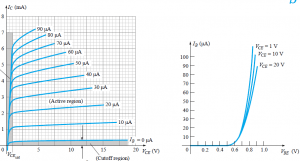
6. From the given characteristics, what is the approximate value of IC at IB=30 uA and VCE=10 V?
a) 3 mA
b) 3.4 mA
c) 0 mA
d) 2 mA
View Answer
Explanation: At the intersection of IB=30 uA and VCE=10 V, IC=3.4 mA.
7. From the given characteristics, what is the approximate value of IC at VBE=0.7 V and VCE=15 V?
a) 3.4 mA
b) 0 mA
c) 2.5 mA
d) 10 mA
View Answer
Explanation: From the characteristics, the value of IB at VBE=0.7V is 20uA. Now, from IB=20 uA, we get IC = 2.5 mA.
8. Which of the following correctly determines the relation between α and β?
a) β=α/(1-α)
b) α=β/(1-α)
c) β=α/(1-β)
d) β=α*(1-β)
View Answer
Explanation: α and β are related as β=α/(1-α).
In a BJT, β = IC/IB. and α = IC/IE
β = αIE/IB = (1+β)α
β = α + αβ
β = α/1-α.
9. The value of IC is precisely zero when the value of IE is zero.
a) True
b) False
View Answer
Explanation: When the value of IE is zero, then the value of IC is equal to ICBO which is in the order of microamperes but not zero.
10. For common emitter configuration, which of the following is the correct relation?
a) IC < IE
b) IC = βIB
c) IC = αIE
d) IC = IE
View Answer
Explanation: All the relations hold true i.e. IC = βIB and IC = αIE. As α<1, hence IC < IE.
Sanfoundry Global Education & Learning Series – Analog Circuits.
To practice all areas of Analog Circuits, here is complete set of 1000+ Multiple Choice Questions and Answers.
If you find a mistake in question / option / answer, kindly take a screenshot and email to [email protected]
- Apply for Electrical & Electronics Engineering Internship
- Apply for Electrical Engineering Internship
- Practice Electrical Engineering MCQs
- Check Electrical Engineering Books
- Practice Electrical & Electronics Engineering MCQs
