This set of Analog Circuits Question Paper focuses on “Frequency Filters – 2”.
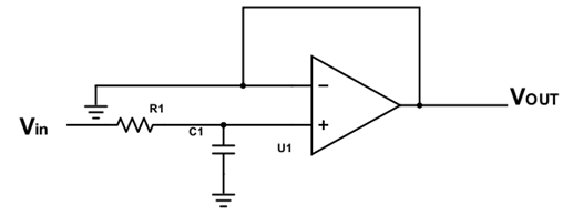
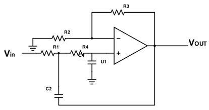
1. Find which one is a sallen-key topology.
a) 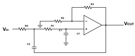
b) 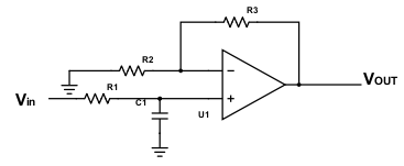
c) 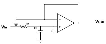
d) 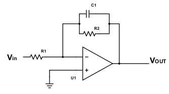
View Answer
Explanation: Sallen-key topology is an electronic filter topology used to implement second-order active filters. It requires a single op-amp for gain control and 4 passive RC components to accomplish the tuning. These are also called positive feedback circuits since the output flows back into non-inverting terminal too.
2. A first-order Butterworth low pass filter is an interconnection of ____________ and ___________
a) Single low pass RC circuit, Voltage follower
b) Low pass RC circuit, Band-pass RC circuit
c) Low pass RC circuit, LC feedback
d) Single low pass RC circuit, Power amplifier
View Answer
Explanation: A first-order Butterworth LPF is an interconnection of a single low pass RC circuit and a voltage follower.
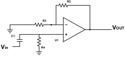
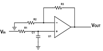
3. Considering a second-order Butterworth LPF using an op-amp, where damping factor = 1.414 find the value of R3, given the following circuit. (R2=5kΩ)
a) 6.71 kΩ
b) 4.22 kΩ
c) 2.93 kΩ
d) 5 kΩ
View Answer
Explanation: Maximum gain, A = 3 – α = 1.586
For the above circuit, the gain is 1 + R3/R2 = 1.586
R3/R2 = 0.586
R3 = 2.93 kΩ.
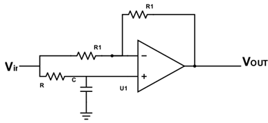
4. For the following circuit, R2=220kΩ, R1=10kΩ, find the maximum gain and the phase shift at the cutoff frequency.
a) Maximum gain = 22, Phase shift = 45°
b) Maximum gain = 23, Phase shift = 135°
c) Maximum gain = 22, Phase shift = 225°
d) Maximum gain = 23, Phase shift = 45°
View Answer
Explanation: Above is a high pass filter, with maximum gain = 1+R2/R1 = 23
Phase shift = tan-1(1) = 45°.
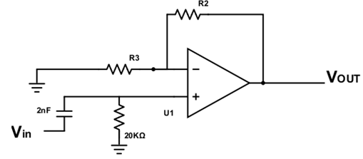
5. Find the cutoff frequency for the following circuit. (R1=R2=20kΩ)
a) 25 kHz
b) 3987 rad/sec
c) 2500 Hz
d) 25000 rad/sec
View Answer
Explanation: Cutoff frequency ωC = 1/RC
ωC = 1000000/20×2 = 25000 rad/s.
6. Given a second-order Butterworth HPF, find the maximum gain magnitude.
a) 1.586 dB
b) 4 dB
c) 2.66 dB
d) 1 dB
View Answer
Explanation: For a second-order Butterworth HPF, the maximum gain AMAX = 3 – α.
α is the damping factor = 1.414
AMAX = 1.586
In dB, the gain is 20 log(1.586) = 4dB.
7. Consider the following circuits.
If a band-pass filter is created by using the above two circuits in cascade, find the correct relation from the choices below.
a) R4C2 >> R1C1
b) R4C2 << R1C1
c) R6R5 = R2C3
d) R4C2 = R1C1
View Answer
Explanation: A band-pass filter can be created as an interconnection of an LPF and an HPF. For this to work, the LPF cut-off frequency should be much greater than the HPF cut-off frequency.
Thus, 1/2π R1C1 >> 1/2π R4C2
Thus R4C2 >> R1C1.
8. Which of these is incorrect for a band-stop filter?
a) An adder is required when designing it using LPF and HPF
b) LPF and HPF are connected in parallel
c) The HPF cut-off frequency should be much higher than LPF cut-off frequency
d) The LPF and HPF are connected in series
View Answer
Explanation: When designing a band-stop filter, a HPF and LPF are connected in parallel, and their output goes into the input of an adder to get the desired output. For correct output, the cut-off frequency of HPF should be much higher than that of the LPF.
9. Which of these is wrong for an all-pass filter?
a) It is used for phase equalization in a communication system
b) It is used in landline communication
c) Its phase shift is -2tan-1RC, between 0 to -180°
d) It can be made using a single op-amp
View Answer
Explanation: An all-pass filter passes all frequencies but provides a different phase shift to each frequency present in the circuit. It is used for phase equalization or delay equalization and is used in landline communication. Following is a circuit of an all-pass filter using a single op-amp.
However, its phase shift is -2tan-1(ωRC)
Sanfoundry Global Education & Learning Series – Analog Circuits.
To practice all questions papers on Analog Circuits, here is complete set of 1000+ Multiple Choice Questions and Answers.
If you find a mistake in question / option / answer, kindly take a screenshot and email to [email protected]
