This set of Analog Circuits Objective Questions & Answers focuses on “Voltage Regulators – 2”.
1. In a power supply, the output voltage can vary due to multiple reasons. Which of these is not true if it is found that the output voltage is constant?
a) The voltage stability factor is very high
b) The output resistance is zero
c) The temperature coefficient is zero
d) The voltage stability factor is very small
View Answer
Explanation: In a power supply, the output voltage can vary due to changes in AC supply, load current and the temperature.
VO = f(VS, IL,T)
ΔVO = SV.ΔVS + ROΔIL + STΔT.
2. Consider the op-amp circuit shown.
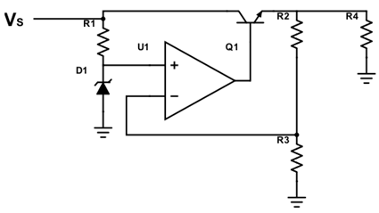
The breakdown voltage of the Zener is 5V. β for the transistor is 100. R1=10kΩ, R2=90kΩ, R3=30kΩ, R4=50kΩ. Calculate the total output voltage.
a) 20V
b) 30V
c) 5V
d) 50V
View Answer
Explanation: VO = VZ(1+R2/R3) = 5(1+90/30) = 5×4
VO = 20V.
3. Consider the following circuit. Find the power dissipation of the transistor given that the diode breakdown voltage is 5V, R1=20kΩ, R2=100kΩ, R3=200kΩ, R4=10Ω. The source voltage VS=20V.
a) 12.12W
b) 9.375W
c) 9.27W
d) 10.575W
View Answer
Explanation: Power dissipation = VCE x IC
VCE = VC – VE = VS – VOUT = 20-5(1+R2/R3) = 20-5×3/2 = 20-7.5 = 12.5V
IC ≈ IE = load current, since R2 and R3 are greater than the load, so most current flows through the load.
IL = VOUT/10 = 0.75A
P = 12.5 x 0.75 = 9.375W.
4. In the Zener controlled series regulator shown below, find the current through the Zener diode.
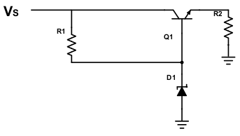
Given that the Zener diode breakdown voltage is 5V, the source voltage is 15V, the output voltage is 10V, R4 = 2kΩ, β=99, R1=2kΩ.
a) 5.05 mA
b) 4.95 mA
c) 3.33 mA
d) 0
View Answer
Explanation: IE = IL = (100)IB
IB = 10/100×2000 = 0.05 mA
Current through R1 = IB + IZ = I1
IZ = I1 -IB = 15-5/2k – 0.05 = 5 – 0.05 = 4.95mA.
5. Consider the circuit shown and find the percentage increase in power dissipation of the transistor if the source voltage increases by 10%.
Given that the breakdown voltage is 5V, R1=10kΩ, R2=100kΩ, R3=200kΩ, R4=10Ω. The source voltage VS=25V.
a) 10%
b) 20.22%
c) 14.28%
d) 15.66%
View Answer
Explanation: Originally, VCE = 25-5 x 3/2 = 17.5V
IC = 7.5/10 = 0.75A
VOUT and IC do not change, only VCE changes.
10% increase in VS means now VS = 110/100 * 25 = 27.5V
VCE = 20V
Power initially P1 = 17.5 x 0.75 = 13.125W
Power finally P2 = 20 * 0.75 = 15W
Power increase % = 15-13.125/13.125*100 = 14.28%.
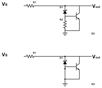
6. The following is a shunt regulator. Find maximum power dissipation of the Zener diode and transistor, given that the source voltage varies from 20-40V, the Zener breakdown voltage is 5V, the output voltage is 10V, the resistance R1=50Ω, R2=20kΩ, β=99, VBE=0.5V.
a) PTransistor = 5.12 W, PZener = 0.051 W
b) PTransistor = 0.41 W, PZener = 0.57 W
c) PTransistor = 5.94 W, PZener = 0.057 W
d) PTransistor = 6.22 W, PZener = 5.66 W
View Answer
Explanation: Output voltage = 10V = VCE
Current across R1 = VS-VO/R1
For maximum power dissipation, supply is maximum
I = 40-10/50 = 0.6A
Current I = IZ + IC = IB + βIB = 100IB
IB = 6mA
IC = 0.594 A
PTransistor = 10*0.594 = 5.94 W
PZener = 10-0.5 * 6mA = 57mA = 0.057 W.
7. What is not related to a transistorized series regulator?
a) The output can be varied by using a variable resistor
b) The output is independent of temperature
c) The overload and short circuit protection is not required
d) The circuit has negative feedback responsible for regulation
View Answer
Explanation: In a transistorized series regulator, the Zener diode maintains emitter voltage. An increase in output is canceled by a decrease in the output. The circuit has negative feedback for this regulation. The output may be varied by using a variable resistor and change in output due to temperature due to the Zener diode is canceled by the change in VBE of the transistor. However, when the load is reduced, or an accidental short-circuit occurs, overload and a short circuit occurs, and protection is needed to prevent that.
8. In a transistorized series regulator, how is the overload and short-circuit protection provided?
a) By the use of a thermistor
b) By using two additional diodes and a current sensing resistor to protect the series transistor
c) By using a diode and an additional resistor to protect the transistor
d) By using a diode along with a capacitor of a small capacitance value in series
View Answer
Explanation: Series transistor can be protected by connecting two additional diodes and a current sensing resistor to the circuit. When the load current is smaller, the diode is off and load current is through the transistor and the new resistor. When the load current increases, the voltage drop across the new resistor increases and soon the diodes start conduction. A limiting current flows through the transistor.
9. What is the output of the IC 7924?
a) 12V
b) -12V
c) 24V
d) -24V
View Answer
Explanation: The IC of series 78xx and 79xx are fixed voltage regulators, wherein the 78 represents those with a positive output and 79 is for those with a negative output. The xx value represents the magnitude of the output voltage being achieved. For proper operation, the input voltage should be at least 2V greater than the output voltage.
10. In the IC 7805, what is the minimum input voltage for proper functioning?
a) 5V
b) 6V
c) 7V
d) 8V
View Answer
Explanation: For a fixed voltage IC regulator, the input voltage should be at least 2V greater than the output voltage. A minimum voltage of 2V should be allowed to drop in the internal circuit of the IC.
Sanfoundry Global Education & Learning Series – Analog Circuits.
To practice all objective questions on Analog Circuits, here is complete set of 1000+ Multiple Choice Questions and Answers.
If you find a mistake in question / option / answer, kindly take a screenshot and email to [email protected]
- Practice Electrical Engineering MCQs
- Check Electrical Engineering Books
- Check Electrical & Electronics Engineering Books
- Apply for Electrical Engineering Internship
- Check Analog Electronics Books
