This set of Analog Circuits Interview Questions and Answers for Experienced people focuses on “Series Clipper-2”.
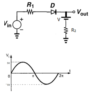
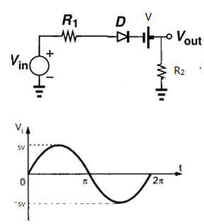
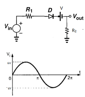
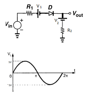
1. In the following clipper circuit resistance R1 and R2 is 1k. Voltage V is 1V. Cut-in voltage of diode is 0.7V. What will be the output of the system if Vin is the signal given below?
(Use constant voltage drop model for diode)
a) 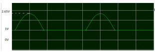
b) 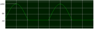
c) 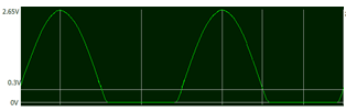
d) 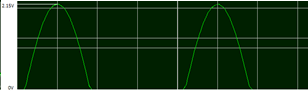
View Answer
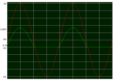
Explanation: Total voltage in the circuit is Vin-VD-V
= 5sint – 0.7 – 1 = 5sint – 1.7
The voltage across resistor R2 = Vtotalx R2/(R1+R2)
= (5sint – 1.7)1/2
Maximum value of output will be 5-1.7/2 = 1.65V
The output will be positive half of sine wave with an upward shift of 1V.
In the diagram below Red is input and green is output
 .
.2. In the following clipper circuit resistance R1 and R2 is 1k. Voltage V is -1V. Cut-in voltage of diode is 0.7V. What will be the output of the system if Vin is the signal given below?
(Use constant voltage drop model for diode)
a)
b)
c)
d)
View Answer
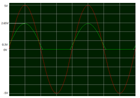
Explanation: Total voltage in the circuit is Vin-VD-V
= 5sint – 0.7 + 1 = 5sint + 0.3
The voltage across resistor R2 = Vtotal x R2/(R1+R2)
= (5sint + 0.3) 1/2
Maximum value of output will be 5+0.3/2 = 2.65V
The output will be positive half of sine wave with a downward shift of 1V.
In the diagram below Red is input and green is output
 .
.3. In the following clipper circuit resistance R1 and R2 is 1k. Voltage V is 1V. Cut-in voltage of diode is 0.7V. What will be the output of the system if Vin is the signal given below?
(Use constant voltage drop model for diode)
a)
b)
c)
d)
View Answer
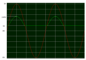
Explanation: Total voltage in the circuit is Vin-VD+V
= 5sint – 0.7 + 1 = 5sint + 0.3
The voltage across resistor R2 = Vtotalx R2/(R1+R2)
= (5sint + 0.3) 1/2
Maximum value of output will be 5+0.3/2 = 2.65V
The output will be positive half of sine wave with maximum voltage of 2.65V
In the diagram below Red is input and green is output.
4. In the following clipper circuit resistance R1 and R2 is 1k. Voltage V is 1V. Cut-in voltage of diode is 0.7V. What will be the output of the system if Vin is the signal given below?
(Use constant voltage drop model for diode)
a)
b)
c)
d)
View Answer
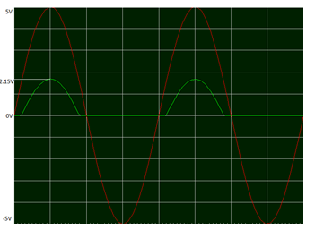
Explanation: Total voltage in the circuit is Vin-VD-V
= 6sint – 0.7 – 1 = 6sint – 1.7
The voltage across resistor R2 = Vtotal x R2/(R1+R2)
= (6sint – 1.7) 1/2
Maximum value of output will be 6-1.7/2 = 2.15V
The output will be positive half of sine wave with reduction of 1.7V and maximum of 2.15V.
In the diagram below Red is input and green is output.
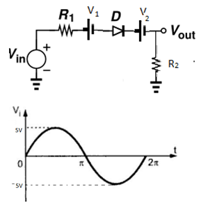
5. In the following clipper circuit resistance R1 and R2 is 1k. Voltage V1 is 1V and V2 is 1.5V. Cut-in voltage of diode is 0.7V. What will be the output of the system if Vin is the signal given below?
(Use constant voltage drop model for diode)
a)
b)
c)
d)
View Answer
Explanation: Total voltage in the circuit is Vin-VD-V1-V2
= 5sint – 0.7 – 1 – 1.5 = 5sint -3.2
The voltage across resistor R2 = Vtotalx R2/(R1+R2)
= (5sint – 3.2) 1/2
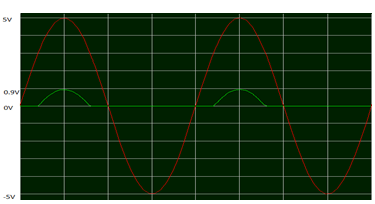
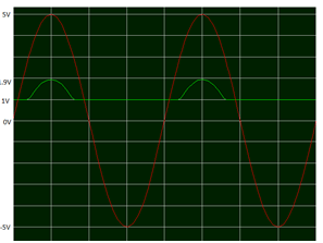
Maximum value of output will be 5-3.2/2 = 0.9V.
The output will be positive half of sine wave with reduction of 3.2V and maximum of 0.9V.
In the diagram below Red is input and green is output.
6. In the following clipper circuit resistance R1 and R2 is 1k. Voltage V1 is -1.5V and V2 is 1V. Cut-in voltage of diode is 0.7V. What will be the output of the system if Vin is the signal given below?
(Use constant voltage drop model for diode)
a)
b)
c)
d)
View Answer
Explanation: Total voltage in the circuit is Vin-VD-V1-V2
= 5sint – 0.7 + 1.5 – 1 = 5sint – 0.2
The voltage across resistor R2 = Vtotalx R2/(R1+R2)
= (5sint – 0.2)1/2
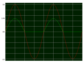
Maximum value of output will be 5-0.2/2 = 2.4V.
The output will be positive half of sine wave with a maximum of 2.4V.
In the diagram below Red is input and green is output.
7. In the following clipper circuit resistance R1 and R2 is 1k. Voltage V1 is 1.5V and V2 is -1V. Cut-in voltage of diode is 0.7V. What will be the output, Vout of the system if Vin is the signal given below?
(Use constant voltage drop model for diode)
a)
b)
c)
d)
View Answer
Explanation: Total voltage in the circuit is Vin-VD-V1-V2
= 5sint – 0.7 – 1.5 + 1 = 5sint – 1.2
The voltage across resistor R2 = Vtotal x R2/(R1+R2)
= (5sint – 1.2)1/2
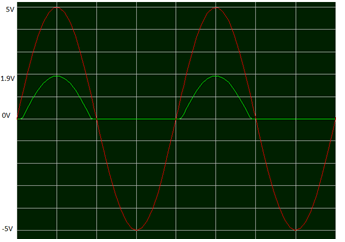
Maximum value of output will be 5-1.2/2 = 1.9V.
The output will be positive half of sine wave with a maximum of 1.9V.
In the diagram below Red is input and green is output.
8. In the following clipper circuit resistance R1 and R2 is 1k. Voltage V1 is 1.5V and V2 is 1 V. Cut-in voltage of diode is 0.7V. What will be the output, Vout of the system if Vin is the signal given below?
(Use constant voltage drop model for diode)
a)
b)
c)
d)
View Answer
Explanation: Total voltage in the circuit is Vin-VD-V1-V2
= 5sint – 0.7 – 1.5 – 1 = 5sint – 3.2
The voltage across resistor R2 = Vtotal x R2/(R1+R2)
= (5sint – 3.2)1/2
Maximum value of output will be 5-3.2/2 = 0.9V.
The output will be positive half of sine wave with a maximum of 0.9V and with an upward shift of 1V.
In the diagram below Red is input and green is output.
Sanfoundry Global Education & Learning Series – Analog Circuits.
To practice all areas of Analog Circuits for Interviews, here is complete set of 1000+ Multiple Choice Questions and Answers.
If you find a mistake in question / option / answer, kindly take a screenshot and email to [email protected]
