This set of Analog Circuits Multiple Choice Questions & Answers (MCQs) focuses on “Frequency Filters – 1”.
1. Which is not a difference between active and passive filter?
a) A passive filter does not use op-amp while an active filter uses an op-amp
b) A passive filter can’t use an inductor while an active filter can
c) A passive filter performs only filtering while an active filter amplifies too
d) A passive filter is used at audio frequency and an active at radio frequency
View Answer
Explanation: A passive filter can consist of all R, L and C elements. An op-amp is used in an active filter, and it also provides amplification along with filtering. There are no inductors used in active filters because they are bigger in size and bulky. Active filters are used at audio frequency and passive filter at radio frequency.
2. In a low pass filter as below, find the cut-off frequency for the following circuit.
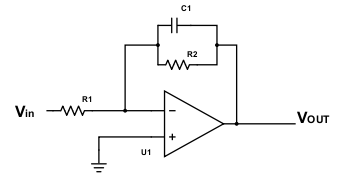
Given that R1=20kΩ, R2=25kΩ, C1=10nF.
a) 640 kHz
b) 636 Hz
c) 5.5 kHz
d) 200 Hz
View Answer
Explanation: The cut-off frequency for the above filter is fc = 1/2πR2C1
fC = 1000000/2π25×10 = 636 Hz.
3. Given that the maximum gain of a low pass filter using op-amp is 5.5 and the resistor R1 = 10kΩ, find the value of R2.
a) 220kΩ
b) 55kΩ
c) 50Ω
d) -55kΩ
View Answer
Explanation: The maximum gain is at low frequencies and at low frequencies, the capacitance reactance is infinite and thus the total feedback impedance ZF = RF = R2
Thus gain = -ZF/Z = -R2/R1
Amplitude = 5.5 = R2/R1 = R2/10k
R2 = 55kΩ.
4. When the input frequency is equal to the cutoff frequency, how much is the phase shift in the output?
a) 180°
b) -135°
c) -45°
d) 135°
View Answer
Explanation: Phase shift = 180° – tan-1f/fC
Phase shift = 180-45 = 135°.
5. For the circuit, calculate the phase shift.
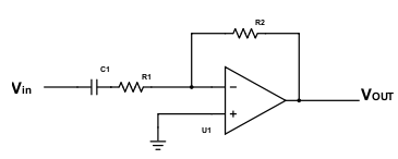
It is given that R1=20kΩ, C1=2nF, R2=22kΩ, and input signal is 2sin6π103t.
a) 233.04°
b) 230.32°
c) 333.04°
d) 129.67°
View Answer
Explanation: Net phase shift is 180 + tan-1fC/f
fc = 1/2πR1C1 = 1000000/2π20×2 = 3.978 kHz
Phase shift = 180 + tan-13.987/3 = 233.04°.
6. What is the frequency response of the filter shown below?
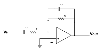
Given R1C1=R2C2.
a) 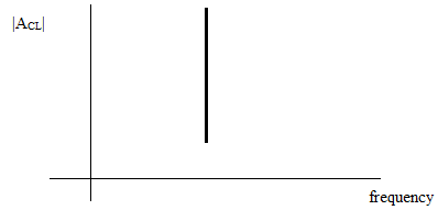
b) 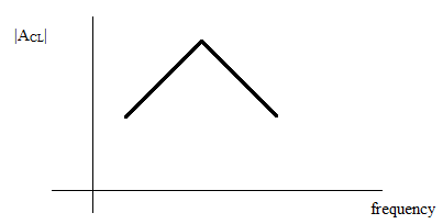
c) 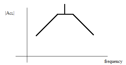
d) 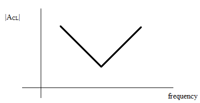
View Answer
Explanation: The given circuit is a bandpass filter. The upper and lower cut-off frequencies depend on the RC constant. However, since R1C1 = R2C2, this means that both the cut-off frequencies are equal. Thus they meet at the same point and form the response as above.
7. Given the following circuit, find the maximum gain.
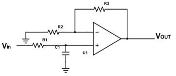
a) 1+R2/R1
b) –R3/R2
c) 1+R3/R2
d) 1+ R1.R3/2
View Answer
Explanation: The above circuit is a low pass filter of the non-inverting type, where the input is at the non-inverting end. The gain is A = 1+R3/R2 / 1+jωR1C1
Thus maximum gain is A = 1+R3/R2.
8. For a low pass filter of non-inverting type, the cutoff frequency is 2kHz and the input frequency is 4kHz. Find the phase shift in output.
a) 117°
b) -117°
c) 243°
d) -63°
View Answer
Explanation: Phase shift = -tan-1f/fC = -tan-12 = -63°.
9. A filter is provided of order 3, find the roll-off rate.
a) 6 dB/decade
b) 60 dB/octave
c) 60 dB/decade
d) 3 dB/decade
View Answer
Explanation: Roll-off rate is the rate at which the gain of a filter decreases outside the pass-band. Roll of rate is increased as the order increases. For an nth order filter, roll-off rate is 20xn dB/decade.
10. Consider the circuit below and find its cut-off frequency.
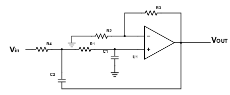
R1=10kΩ, R2=20kΩ, R3=30kΩ, C1=2nF, C2=4nF, R4=15kΩ.
a) 4.6 kHz
b) 6.2 kHz
c) 5.5 kHz
d) 4.2 kHz
View Answer
Explanation: fC = \(\frac{1}{2π\sqrt{R4.R1.C1.C2}}\)
fC = 4.6 kHz.
Sanfoundry Global Education & Learning Series – Analog Circuits.
To practice all areas of Analog Circuits, here is complete set of 1000+ Multiple Choice Questions and Answers.
If you find a mistake in question / option / answer, kindly take a screenshot and email to [email protected]
- Apply for Electrical Engineering Internship
- Check Electrical Engineering Books
- Apply for Electrical & Electronics Engineering Internship
- Practice Electrical Engineering MCQs
- Check Electrical & Electronics Engineering Books
