This set of Analog Circuits Multiple Choice Questions & Answers (MCQs) focuses on “Piecewise Linear Model of Diode-2”.
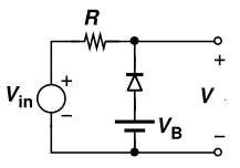
1. In the given circuit input voltage Vin is 3V and VB is 1.5V. The resistance R is 1.5K. Cut-in voltage of diode is 0.5V. Forward bias resistance is 10Ω. The Voltage V will be ____________
a) 2.7V
b) 3V
c) 0.8V
d) 1.5V
View Answer
Explanation: In piecewise linear model, we can consider diode as a voltage source of 0.5V along with an ideal diode. VIN being applied is 3V, which is greater than 1.5-0.5 V, and hence the diode is reverse biased and input appears at output.
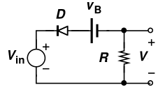
2. In the circuit shown below voltage Vin is 3V and VB is 2V. The resistor R is 1K. Cut-in voltage of diode is 0.7V. The voltage V is __________
a) 0.3V
b) 1V
c) 3V
d) 0V
View Answer
Explanation: In piecewise linear model, we can consider diode as a voltage source of 0.7V along with an ideal diode. VIN being applied is 3V, which is greater than 2-0.7 V, and hence the diode is reverse biased and considering it open, no output is obtained.
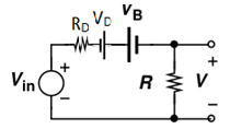
3. In the circuit shown below voltage Vin is -3V and VB is -2V. The resistor R is 1K. Cut-in voltage of diode is 0.7V. Forward bias resistance is 10Ω. The voltage V is __________
a) -0.29V
b) -4.25V
c) 4.25V
d) 2.9V
View Answer
Explanation: Effective voltage across diode is one volt. Hence diode is in forward bias mode. So we can apply equivalent circuit of diode.
Net voltage through R and RD is -3-2+0.7 = -4.3V
Current through the circuit is -4.3/(R+RD) = -4.3/(1010) = -0.00425A=-4.25 mA
Hence voltage across R is 1Kx(-4.25mA) = -4.25V.
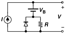
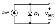
4. In the circuit shown below current I is 2mA and VB is 1V. The resistor R is 1K. Cut-in voltage of diode is 0.7V. Forward bias resistance is 10Ω. The voltage V is __________
a) 3V
b) 2V
c) 1V
d) 0.3V
View Answer
Explanation: Since current source is reverse bias to the diode current passes through resistor R. Voltage across resistor R is 2mA x 1k = 2V. Since resistor and diodes are parallel net output voltage V is VB + voltage across resistor R = 1+2 = 3V.
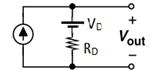
5. In the circuit shown below current I is 2mA and VB is -1V. The resistor R is 1K. Cut-in voltage of diode is 0.7V. Forward bias resistance is 10Ω. The voltage V is __________
a) 1.3V
b) 0.3V
c) 1V
d) 2V
View Answer
Explanation: Since current source is reverse bias to the diode current passes through resistor R. Voltage across resistor R is 2mA x 1k = 2V. Since resistor and diodes are parallel net output voltage V is VB + voltage across resistor R = -1+2 = 1V.
6. In the circuit shown below voltage Vin is 3V and VB is 1V. The resistor R1 and R2 are 1K. Assume both diodes are identical. Forward bias resistance is 10Ω. Cut-in voltage of diode is 0.7V. The voltage Vout is __________
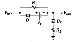
a) 1.235V
b) 0.234V
c) 1.314V
d) 1.564V
View Answer
Explanation: Since D1 and D2 are forward biased we can replace them with their equivalent diagram.
Assume I be the current through the circuit. By kirchoff’s voltage rule,
Vout = -VD+IRD+IR2 ————(1)
Current through R1 (Vin-Vout)/1k = (3-Vout)/1k
Current through diode is (Vin-Vout-VD-VB)/RD = (0.3-Vout)/10
Total current I = (3-Vout)/1000+(1.3-Vout)/10 = 1.330-1.010Vout
Substitute this in eq(1)
That is, Vout = -0.7 + 1010(1.33-1.01Vout)
1021Vout = 1342. Therefore, Vout = 1.314V.
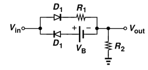
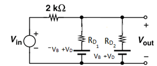
7. In the circuit shown below voltage Vin is -3V and VB is -1V. The resistor R1 and R2 are 1K. Assume both diodes are identical. Forward bias resistance is 10Ω. Cut-in voltage of diode is 0.7V. The voltage Vout is __________
a) -2V
b) -3V
c) -1V
d) -.0.7V
View Answer
Explanation: Since both diodes are in reverse bias mode applied voltage Vin will appear on Vout. Diode D1 and D2 disappears and leaves the terminal as open.
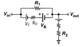
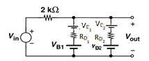
8. In the circuit shown below voltage Vin is 3V and VB is 1V. The resistor R1 and R2 are 1K. Assume both diodes are identical. Forward bias resistance is 10Ω. Cut-in voltage of diode is 0.7V. The voltage Vout is __________
a) 1.14V
b) 1.23V
c) 0.32V
d) 1.34V
View Answer
Explanation:
Assume I be the current through the circuit. By kirchoff’s voltage rule,
Vout = IR2 ————(1)
Current through R1 (Vin-Vout-VD)/1.01k = (2.3-Vout)/1010
Current through diode D2 is 0 since D2 is in reverse bias mode.
current I = (2.3-Vout)/1010
Substitute this in eq(1)
That is, Vout = (2.3-Vout)/1010 x 1000 => 1.99Vout = 2.27 => Vout = 2.27/1.99 = 1.144V.
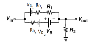
9. In the circuit shown below voltage Vin is 3V and VB1 is -1V and VB2 is 1V. Assume both diodes are identical. Cut-in voltage of diode is 0.7V. Forward bias resistance is 10Ω. The voltage Vout is __________
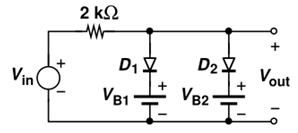
a) 0.6V
b) 1V
c) 1.7V
d) 2V
View Answer
Explanation: In this condition both diodes are forward biased
This circuit can be further reduced to by assuming VB as 1V
By network analysis using kirchoff’s voltage rule current through RD2 will be 0.09A.
The voltage in Vout will be VB+VD-0.09×10 = 0.6V.
10. In the circuit shown below, cut-in voltage of diode is 0.7V. Forward bias resistance is 10Ω. The voltage V is?
a) 0.69V
b) 0.7V
c) 0.68V
d) 0.72V
View Answer
Explanation: Since diode is in forward bias we can replace diode with voltage source of 0.7V and resistor of resistance 10Ω.
Vout will be IRD+VD = 2mAx10 + 0.7 = 0.72V.
Sanfoundry Global Education & Learning Series – Analog Circuits.
To practice all areas of Analog Circuits, here is complete set of 1000+ Multiple Choice Questions and Answers.
If you find a mistake in question / option / answer, kindly take a screenshot and email to [email protected]
- Check Electrical & Electronics Engineering Books
- Check Electrical Engineering Books
- Check Analog Electronics Books
- Practice Electrical Engineering MCQs
- Apply for Electrical Engineering Internship
