This set of Analog Circuits Multiple Choice Questions & Answers (MCQs) focuses on “Piecewise Linear Model of Diode – 1”.
1. After cut-in voltage in piecewise linear model diode act as a ___________
a) Resistor
b) Capacitor
c) Conductor
d) Insulator
View Answer
Explanation: After cut –in voltage diode act as a resistor in piecewise linear mode. In normal operation diode current is exponentially related to voltage.
2. Reverse biased condition of a diode in piecewise linear model is equivalent to __________
a) Resistor
b) Capacitor
c) Conductor
d) Insulator
View Answer
Explanation: For a diode in reverse bias mode current through the diode is in micro amperes or nano amperes. Hence we can assume it as zero. In piecewise linear model reverse current is assumed to zero. That is, as an insulator.
3. Voltage drop produced by a diode in piecewise linear mode is __________
a) Constant and equal to knee voltage
b) Varies linearly with voltage after knee voltage
c) Varies exponentially with voltage after knee voltage
d) Constant and equal to twice of knee voltage
View Answer
Explanation: Voltage drop produced by diode in piecewise linear model is not constant. Since it contains effect of resistor, the diode voltage linearly increases as input voltage increases.
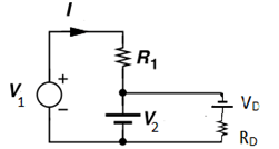
4. In the given circuit voltage V = 2V.cut-in voltage of diode is 0.7V. Forward resistance is 10Ω. The current I through the circuit is ____________
(Assume piecewise linear model for diode)
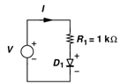
a) 0.235mA
b) 1.29mA
c) 1.63mA
d) 2.27mA
View Answer
Explanation: Since diode is in forward bias mode it can replaced by the equivalent circuit
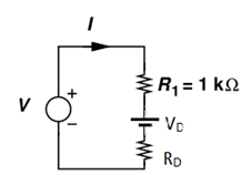
I = (V-VD)/R1+RD
= (3-0.7)/1010 = 2.27mA.
5. In the given circuit input voltage Vin is 3V and V2 is 1V. The resistance R1 is 1.5K. Cut-in voltage of diode is 0.5V. Forward bias resistance is 10Ω. The current I will be __________
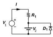
a) 2.03mA
b) 0.23mA
c) 1.58mA
d) 1.33mA
View Answer
Explanation: Since both voltage sources are reverse bias to the diode, diode in the circuit disappears and equivalent circuit becomes as follows
So current I = V1-V2/R
= 3-1/1.5k = 1.33mA.
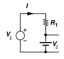
6. In the given circuit input voltage V1 is -3V and V2 is -1V. The resistance R1 is 1K. Cut-in voltage of diode is 0.5V. Forward bias resistance is 10Ω. The approximate current I is _________
(Use piecewise linear model of diode)
a) -1mA
b) -2mA
c) -0.2mA
d) -0.1mA
View Answer
Explanation: Since both voltage sources are in forward bias to diode, the equivalent circuit will be as follows
Since voltage across diode is 1V. current I = -3+1/1k = -2mA.
7. In the given circuit input voltage V is 2V and VB is 1V. The resistance R1 and R2 is 1K. Cut-in voltage of diode is 0.5V. Forward bias resistance is 10Ω. The current I will be
(Use piecewise linear model of diode)
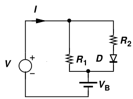
a) 0.29mA
b) 0.21mA
c) 0.36mA
d) 0.15mA
View Answer
Explanation: Since V-VB = 1V forward biases the diode, we can use equivalent circuit of diode as follows
Current through R1, I1 = 1V/R1 = 1mA.
Current through R2, I2 = (1-VD)/(R2¬+RD) = (1-0.7)/1010 = 0.297mA.
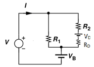
8. In the given circuit input voltage V is 3V and VB is 1V. The resistance R1 and R2 is 1K. Cut-in voltage of diode is 0.5V. Forward bias resistance is 10Ω. The current I will be
(Use piecewise linear model of diode)
a) 0.96mA
b) 2.13mA
c) 1.56mA
d) 1.23ma
View Answer
Explanation: Since diode is in forward bias we can assume equivalent circuit model and assume following circuit
Let voltage across diode is V0 now voltage across branch is V-V0
Current I = (2-V0)/R1 + (2-V0-VB)/R2 = (2-V0)/1000+((1-V0))/1000 …………………….(1)
V0 = VD + IRD = 0.7+10I
Put this value in eq(1)
That is, I = (2-0.7-10I)/1000+((1-0.7-10I))/1000 => 1000I = 1.6 – 20I => 1020 I = 1.6
That is, I = 1.6/1020 = 1.56mA.
9. In the given circuit input voltage V is -3V and VB is 1V. The resistance R1 and R2 is 1K. Cut-in voltage of diode is 0.5V. Forward bias resistance is 10Ω. The current I will be
(Use piecewise linear model of diode)
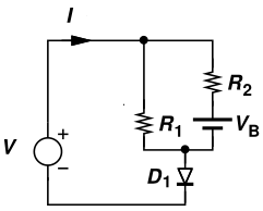
a) 1.2mA
b) 0mA
c) 0.8mA
d) 1mA
View Answer
Explanation: If we suppose diode to be forward biased then voltage across R1 is -2.5V and current flows from bottom to top in that link. For source VB current flows the same but then KCL can’t be applied at the top node since all currents are incoming. Hence the diode is reverse biased and is an open circuit. No current flows through it and I=0.
10. In the given circuit input voltage Vin is 3V and VB is 1V. The resistance R is 1K. Cut-in voltage of diode is 0.5V. Forward bias resistance is 10Ω. The current I will be? (Use piecewise linear model of diode)
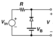
a) 1V
b) 3V
c) 2.3V
d) 1.3V
View Answer
Explanation: If we consider diode as a short circuit, the voltage in circuit is thus 3-1=2V and current flows from top to bottom across diode. But that only happens in a reverse bias of the diode. Hence the diode is in reverse bias and open. Output voltage V=3V.
Sanfoundry Global Education & Learning Series – Analog Circuits.
To practice all areas of Analog Circuits, here is complete set of 1000+ Multiple Choice Questions and Answers.
If you find a mistake in question / option / answer, kindly take a screenshot and email to [email protected]
- Check Analog Electronics Books
- Practice Electrical Engineering MCQs
- Apply for Electrical Engineering Internship
- Check Electrical & Electronics Engineering Books
- Check Electrical Engineering Books
