This set of Analog Circuits Multiple Choice Questions & Answers (MCQs) focuses on “Different Types of Multivibrators – 2”.
1. Given the following circuit.
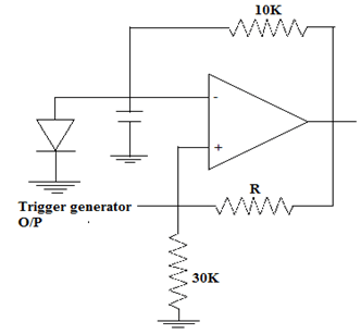
The supply voltage being applied is ±15V. The diode cut-in voltage is 0.7V. Find the maximum value of R such that circuit can behave as a monostable multivibrator.
a) 612.8kΩ
b) 33kΩ
c) 220.22kΩ
d) 450.8kΩ
View Answer
Explanation: The condition to be followed is βVSat > VY.
β = R1/R1+R2 = 30k/30k+R
Thus (30k/30k+R). 15 > 0.7
450k/30k + R > 0.7
30k+R < 642.85k
R < 612.8kΩ.
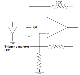
2. For the given circuit, find the time period of the output waveform, given that the diode is used is of Silicon and the supply voltage being applied is ±15V. The feedback factor is 0.4.
a) 11.12 ms
b) 12.4 ms
c) 11.2 seconds
d) 5.6 ms
View Answer
Explanation: T = RCln(1+Vγ/VSat/1-β)
T = 10x2x10-3xln((1+0.7/15)/0.6) = 20×10-3ln(1.0467/0.6)=20×0.556×10-3
T = 11.12 ms.
3. Find the approximate frequency of output waveform of a monostable multivibrator given that RC = 20×10-3 and feedback factor = 0.3.
a) 200Hz
b) 142Hz
c) 233Hz
d) Can’t be found out without supply voltage value
View Answer
Explanation: T = RCln(1/1-β)
T = 20×10-3 x ln(1/0.7) = 20×0.35×10-3 = 7ms
f = 0.142 kHz = 142 Hz.
4. Consider the circuit shown below.
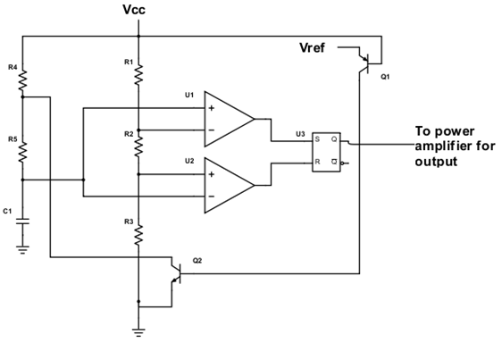
R1=5kΩ, R2=5kΩ, R3=5kΩ, R4=10kΩ, R5=20kΩ, C1=10μF. Calculate the total charging time and discharging time.
a) The charging time = 0.2 seconds, the is charging time is 0.2 seconds
b) The charging time = 0.3 seconds, the discharging time is 0.2 seconds
c) The charging time = 0.3 seconds, the discharging time is 0.3 seconds
d) The charging time = 0.5 seconds, the discharging time is 0.4 seconds
View Answer
Explanation: Discharge time = R5.C1 = 20x10x10-3 = 0.2 seconds
Charging time = (R4+R5)C1 = 30x10x10-3 = 0.3 seconds.
5. For the given circuit, find the duty cycle of the output.
R4=30kΩ, R5=25kΩ.
a) 0.6875
b) 0.7211
c) 0.5681
d) 0.5010
View Answer
Explanation: Duty cycle = THigh/TO
Duty cycle = R4+R5/R4+2xR5
Duty cycle = 55/80= 0.6875.
6. What is the output frequency for the following circuit?
R4=30kΩ, R5=40kΩ, C1=5nF.
a) 2.63 kHz
b) 3kHz
c) 263 kHz
d) 4.4 kHz
View Answer
Explanation: Output frequency = 1.45/(R4+2xR5)xC1
fO = 1.45×1000000/110×5 = 2.63 kHz.
7. In the astable multivibrator using IC 555, it can be used as a voltage to frequency converter.
a) True
b) False
View Answer
Explanation: An astable multivibrator can be easily used as a voltage controlled oscillator or as a voltage to frequency converter if a control voltage is applied to the control pin of the IC. The control pin is usually grounded through a capacitor if unused.
8. How can a monostable multivibrator using IC 555 be used as a PWM generator?
a) If a diode is connected across the resistor RA
b) If a modulating signal m(t) is applied at the control pin
c) If the control pin is always kept high
d) It cannot be used as a PWM generator ever
View Answer
Explanation: A monostable multivibrator can be used as a PWM generator if a modulating signal is applied to the control pin. The control pin is used to vary the voltage at the inverting node of the upper comparator. If unused, then the control pin is grounded through a capacitor.
9. Given that the charging current of capacitor is constant in a monostable multivibrator using IC 555, then find the type of output waveform, type of capacitor voltage waveform and the time period of output.
a) The capacitor waveform is a ramp, the output waveform is sinusoidal, the time period is \(\frac{2.C.VCC}{3.I}\)
b) The capacitor waveform is a ramp, the output waveform is a pulse, the time period is \(\frac{2.C.VCC}{3.I}\)
c) The capacitor waveform is a ramp, the output waveform is a pulse, the time period is \(\frac{C.VCC}{3.I}\)
d) The capacitor waveform is a ramp, the output waveform is a ramp, the time period is \(\frac{2.C.VCC}{3.I}\)
View Answer
Explanation: If a constant charging current is applied through the capacitor, the output is a pulse, while capacitor voltage is a ramp.
Time period of ramp/pulse = TO = 2VCCxC/3I.
Sanfoundry Global Education & Learning Series – Analog Circuits.
To practice all areas of Analog Circuits Problems, here is complete set of 1000+ Multiple Choice Questions and Answers.
If you find a mistake in question / option / answer, kindly take a screenshot and email to [email protected]
- Check Analog Electronics Books
- Apply for Electrical Engineering Internship
- Check Electrical Engineering Books
- Check Electrical & Electronics Engineering Books
- Practice Electrical Engineering MCQs
