This is a PLC Program to Implement T Flip Flop.
Problem Description
Implementing T(Toggle) Flip Flop in PLC using Ladder Diagram programming language.
Problem Solution
- The T Flip Flop has two inputs.
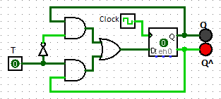
- One is the Clock Input and the other one is T input. Clock input initiates the Flip Flop action. The second input T input enables or disables the trigger operation. Circuit diagram of T Flip Flop is shown in figure below.
Realization of T Flip Flop using gates and D Flip Flop
Truth table for the T Flip Flop
T  Clock Qn Qn+1
0  0     X  Qn
0  1	 X  Qn
1  0	 Q  Qn
1  1	 Q  Q^
- A High state in the clock column indicates that the clock generates square waves making a 0 to 1 and 1 to 0 transitions.
- The Qn column is the state of the flip flop prior to the clock application and the Qn+1 column is the state of the flip flop after the clock.
- An x indicates don’t care condition.
- Ladder Logic Diagram of this can be obtained by creating One Shot of T Input.
- This can be done in PLCs such as Allen Bradley directly by using OSR instruction. OSR stands for One Shot Rise which when input is given, it simply triggers an event to occur one time.
- Many PLCs do not have this instruction. By adding one more extra relay or by storing bit status keeping in mind the scan cycle and order of rungs in programming, One Shot can be obtained.
PLC Program
Here is PLC program to Implement T Flip Flop, along with program explanation and run time test cases.
advertisement
advertisement
List of Inputs and Outputs
 T(Toggle)  	  =	I:1/0	(Input)
 Qn Output/Light  =	O:2/0	(Output)
 Relay Bit  	  =	B3:0/0	(Bit 0 Output)
 One Shot	  =	O:2/1	(OS logic Output)
 OSR Bit	  =	B3:0/15	(OSR instruction)
Ladder Diagram to obtain output Figure 1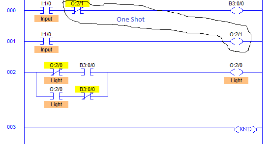
Ladder Diagram to obtain output Figure 2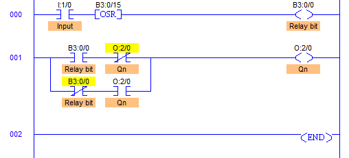
Note: Assuming Clock is always present, so it only depends on the state of T input as stated in Truth Table of T Flip Flop above.
Program Description
- I:1/0 is T input which is used to toggle the output.
- We are assuming that the clock is always present, so output is dependent only on T input I:1/0.
- In the Ladder Diagram Figure. 1, One Shot is created by ordering rungs such a way that during first scan cycle when T input I:1/0 is triggered, Bit B3:0/0 goes high immediately setting output image table of B3:0/0 to 1.
- During first scan cycle, it first scans the RUNG000 and then RUNG001.
- When the RUNG002 is scanned, it receives input “1” from the image table which was set while scanning RUNG000. It triggers output O:2/0.
- As soon as output O:2/0 goes high, it is sealed.
- During the second scan cycle, when RUNG000 is scanned, status of O:2/1 is observed “1” which breaks the flow in RUNG000 resetting image table of memory bit B3:0/0 to “0”.
- This does not occur output O:2/0 to be de-energized due to latching logic.
- Even if the T input is withdrawn, the output O:2/0 does not change.
- When T input I:1/0 is again triggered, it repeats the same scan cycle sequence De-Energizing output O:2/0.
- The only difference in Ladder Diagram of Figure.1 and Figure.2 is that in Figure.1, one extra rung is added to create One Shot but the same rung is eliminated in Figure.2 by using One Shot Rise instruction.
- Operation remains the same.
Runtime Test Cases
T Clock	Qn Qn+1	Comments
0 0	X  Qn	Clock is not present
0 1	X  Qn	Unchanged output
1 0	Q  Qn	Output Toggles
1 1	Q  Q^	Output Toggles
Sanfoundry Global Education & Learning Series – PLC Algorithms.
To practice all PLC programs, here is complete set of 100+ PLC Problems and Solutions.
advertisement
