This is a PLC Program for Continuous Stirred Tank Reactor.
Problem Description
Control Continuous Stirred Tank Reactor of a chemical plant. Implement automation to control this CSTR in PLC using Ladder Diagram programming language.
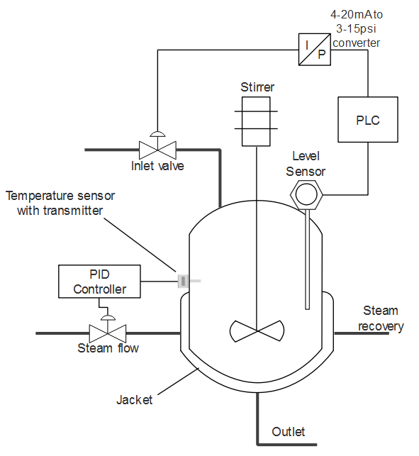
Problem Diagram
Problem Solution
- Basically three parameters are controlled in this reactor. Temperature, Flow and Level of the tank.
- Temperature controlling is best done by PID Temperature controller, so in many industries, controlling of Temperature is assigned to PID control loop as shown in the diagram above.
- Continuous level measurement is required. To do this, capacitance level measurement technique is used because the tank may be Open or Close depending upon the process application. Capacitance Measurement method works for both Open and Closed tanks.
- Capacitance Level Measurement sensor comes along with Transmitter to convert level output into equivalent standard current signal 4-20mA. If level sensor does not have a transmitter, calibration has to be done in order to achieve 4mA for Low level and 20mA for High level.
- Analog I/O Modules are used to deal with analog input signals and analog output final control elements.
- To process data, necessary conversions are made on the basis of desired output requirement.
PLC Program
Here is PLC program for Continuous Stirred Tank Reactor, along with program explanation and run time test cases.
List of Inputs and Outputs
 I:1/14	= Start							(Input)
 I:1/15	= Stop							(Input)
 O:2/15	= Latching Coil						(Output)
 DIV	= Division by the value which is changed per centimetre	(Compute)
 MUL	= Multiplication					(Compute)
 MOV	= Move instruction to move data			        (Logical)
 I:3	= Input from transmitter				(Input)
 N7:0	= Input data stored in Hex form				(Register)
 N7:1	= Storing computed value				(Register)
 N7:2	= Storing conversion of preset cms into equivalent hex	(Register)
 O:3	= Output to which I-P converter is connected		(Output)
Ladder Diagram to control CSTR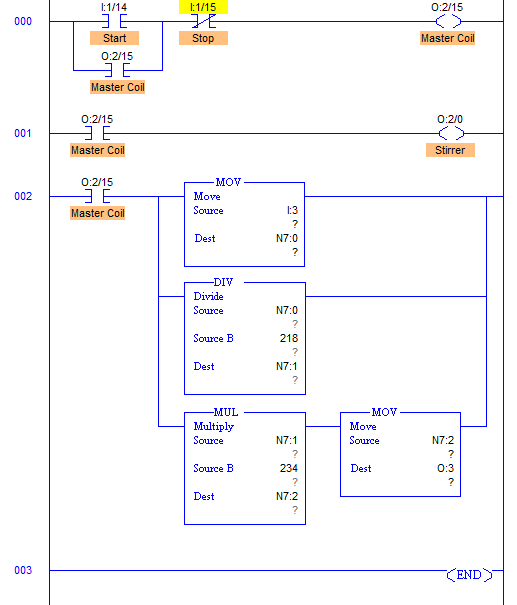
advertisement
advertisement
Program Description
- RUNG001 comprises all the conversion needed to control level of the tank.
- Output of transmitter is in current signals which is 4-20mA.
- When output is 4mA, Analog Input Module converts it into 16bit equivalent hex numbers. Hence when input at I:3 to Analog module is 4mA, it moves 0000h into register and when 20mA, it moves FFFFh into register. Here register N7:0.
- Here height of the tank is 3m or 300cm. By converting it into equivalent hex, change in value per centimeter is 218.
- Value of N7:0 is then multiplied with 234 because when Level reaches 280cm, output is 61167 in decimal (EEEFh). So when output at 280cm is multiplied with 234, we get full FFFFh at N7:2 to operate valve to fully close.
- This multiplication is stored into N7:2 register. Digital to Analog conversion of value stored in N7:2 is performed inside the processor and equivalent mA current is received from terminal O:3.
- Current to Pneumatic converter then converts current signals into equivalent 3-15psi pneumatic signal and adjusts valve opening.
Runtime Test Cases
Inputs	        Outputs  	Physical Elements
I:3 = 0000h	O:3 = 0000h	Valve fully open
I:3 = EEEFh	O:3 = FFFFh	Valve fully closed
I3 = 7778h	O:3 = 8000h	Valve 50% open
Sanfoundry Global Education & Learning Series – PLC Algorithms.
To practice all PLC programs, here is complete set of 100+ PLC Problems and Solutions.
