This is a PLC program to implement Excess-3 to BCD converter.
Problem Description
Implementing Excess-3 to BCD conversion in PLC using Ladder Diagram programming language
Problem Solution
- BCD can be derived from Excess-3 code by reversing the process used in conversion of BCD to Excess-3 code which is to subtract 0011 or 0011 0011 from given BCD number.
- For example, Decimal number 12 is represented as 0100 0101 in Excess-3 code. If we subtract 3 (0011 0011) from given Excess-3 code, then the corresponding BCD is 0001 0010.
- Write the truth table relating Excess-3 and BCD.
- Write Karnaugh-Map for each output and obtain simplified expression.
- Implement Excess-3 code to BCD converter using Logic Gates.
- Implement Logic Gates’ circuit in PLC using Ladder Diagram programming language.
Truth Table relating BCD and Excess-3 codes
Decimal	Excess-3 inputs	                BCD outputs
	E3	E2	E1	E0	B3	B2	B1	B0
0	0	0	0	0	x	x	x	x
1	0	0	0	1	x	x	x	x
2	0	0	1	0	x	x	x	x
3	0	0	1	1	0	0	0	0
4	0	1	0	0	0	0	0	1
5	0	1	0	1	0	0	1	0
6	0	1	1	0	0	0	1	1
7	0	1	1	1	0	1	0	0
8	1	0	0	0	0	1	0	1
9	1	0	1	1	0	1	1	0
10	1	0	1	0	0	1	1	1
11	1	0	0	1	1	0	0	0
12	1	1	0	0	1	0	0	1
13	1	1	0	1	x	x	x	x
14	1	1	1	0	x	x	x	x
15	1	1	1	1	x	x	x	x
Boolean expression for each Excess-3 code bits
B3= m(	11, 12) + d (0, 1, 2, 13, 14, 15)
B2= m(7, 8, 9, 10) + d (0, 1, 2 13, 14, 15)
B1= m(5, 6, 9, 10) + d (0, 1, 2 13, 14, 15)
B0= m(4, 6, 8, 10, 12) + d (0, 1, 2 13, 14, 15)
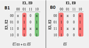
Karnaugh-Map for each output
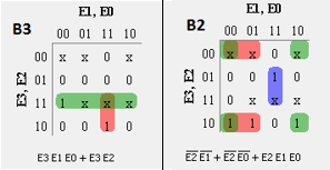
Realizing code conversion using Logic Gates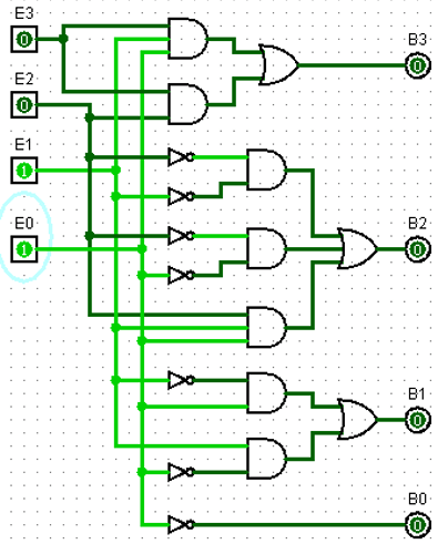
advertisement
advertisement
PLC Program
Here is PLC program to implement Excess-3 to BCD converter, along with program explanation and run time test cases.
List of Inputs and Outputs
 E3=				I:1/0	(Input)
 E3=				I:1/1	(Input)
 E1=				I:1/2	(Input)
 E0=				I:1/3	(Input)
 B3=				O:2/0	(Output)
 B2=				O:2/1	(Output)
 B1=				O:2/2	(Output)
 B0=				O:2/3	(Output)
Ladder Diagram to obtain Excess-3 code output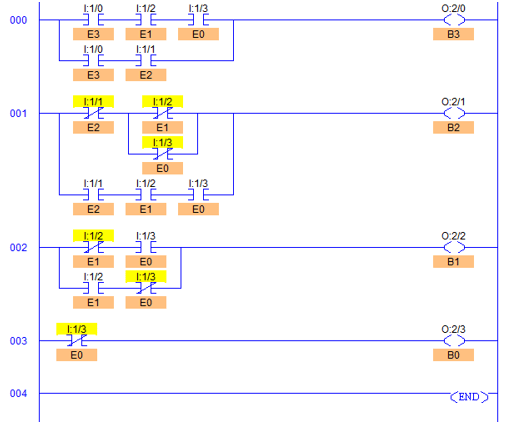
Program Description
- By simply reversing the process of BCD to Excess-3 Code conversion, BCD can be derived from given Excess-3 code.
- RUNG000 to RUNG003 are for BCD bits B3 to B0 respectively.
- Simplified expression is converted into Logic Circuit and the circuit is implemented in Ladder Diagram as shown in fig above.
- RUNG000 is for B3 in which two AND gates and output of these gates are ORed together to form bit B3. I:1/0, I:1/2, I:1/3 are connected in series as an AND gate and I:1/0, I:1/1 are connected similarly in series.
- Output of these AND gates (E3E2E1 and E3E2) are connected in parallel to each other contributing as OR function.
- Similarly all other inputs in Rungs are connected.
Runtime Test Cases
Decimal	Excess-3 inputs	                BCD outputs
	E3	E2	E1	E0	B3	B2	B1	B0
3	0	0	1	1	0	0	0	0
4	0	1	0	0	0	0	0	1
5	0	1	0	1	0	0	1	0
6	0	1	1	0	0	0	1	1
7	0	1	1	1	0	1	0	0
8	1	0	0	0	0	1	0	1
9	1	0	1	1	0	1	1	0
10	1	0	1	0	0	1	1	1
11	1	0	0	1	1	0	0	0
12	1	1	0	0	1	0	0	1
Sanfoundry Global Education & Learning Series – PLC Algorithms.
advertisement
To practice all PLC programs, here is complete set of 100+ PLC Problems and Solutions.
If you find any mistake above, kindly email to [email protected]