This is a PLC Program to Perform Pulse Width Modulation.
Problem Description
Implement Pulse Width Modulation in PLC using Ladder Diagram programming language.
Problem Solution
- To perform this two timers are used to Turn ON and OFF an output according to the length of a pulse.
- Timer preset value should vary such that when preset of one timer is increased, preset value of other timer should decrease in order to maintain Turn ON and OFF time of output.
- Select input bits such that we can directly enter digits and place it into Preset value of a timer.
- This can be done by using a digital input device which generates 0-9 numerical digits.
- Output of this Digital device is always in BCD form and Timers preset values store data in Hexadecimal, so whichever data are sent to preset register of a time, it has to be converted into Hexadecimal form.
- FRD instruction can be used to perform BCD to Hex conversion.
- Output of this conversion is directly moved to preset register of timer which can be performed by MOV instruction.
PLC Program
Here is PLC program to Perform Pulse Width Modulation, along with program explanation and run time test cases.
List of Inputs and Outputs
 I:1/0	  = Master Start PB 			(Input)
 I:1/1	  = Master Stop PB			(Input)
 O:2/15	  = Master Coil				(Output)
 T4:0	  = Timer 0, ON time			(Timer)
 T4:0.PRE = Timer 0 Preset value address	(Timer)
 T4:1	  = Timer 1, OFF time			(Timer)
 T4:1.PRE = Timer 1 Preset value address	(Timer)
 -(RES)-  = Timer reset coil			(Output)
 I:5	  = 0-100 BCD input			(Input)
 N7:1	  = BCD-Hex conversion storing register	(Register)
Ladder Diagram to perform PWM operation
Program Description
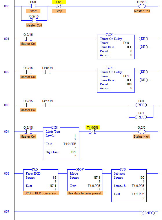
- RUNG000 to RUNG003 are used for timers T4:0 and T4:1 which can be understood easily.
- RUNG004 is for output to which Pulse of a particular width is provided.
- I:5 is used to give 2 digit input to preset value address which alters Preset of Timer T4:0 and determines ON time of output O:2/0.
- Preset value of T4:1 depends on T4:0.PRE.
- 2 digit output has a limit from 0-99, hence subtraction is performed to set the preset value of T4:1 timer which is OFF time of output O:2/0.
- This input is BCD number.
- Data stored in any registers in PLC are in the form of Hexadecimal. So BCD input from I:5 has to be converted into Hexadecimal which is performed by FRD instruction and moved to address T4:0.PRE.
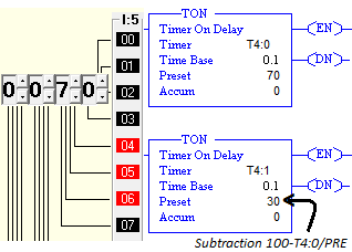
- Now when 2 digit input is set as a preset of Timer T4:0, it is subtracted from 100 and the output is set as a preset of Timer T4:1.
- 100 – ON time = OFF time. (ON time = 0-99)
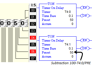
- If the input is 50, then both the timers hold the same value, hence square wave of 50% duty cycle is obtained.
- So by varying input from 0-99, width of pulse (ON time of output) is varied.
- However, when input from I:5 is 0 and OFF time is completed, output O:2/0 blinks for a while. To eliminate this error, LIM instruction is used.
- We can even use 3 and 4 digit inputs but then these digits must be subtracted from 1000 and 10000 respectively.
Runtime Test Cases
Sanfoundry Global Education & Learning Series – PLC Algorithms.
To practice all PLC programs, here is complete set of 100+ PLC Problems and Solutions.
advertisement
advertisement


