This is a PLC Program to Maintain Level of a Tank.
Problem Description
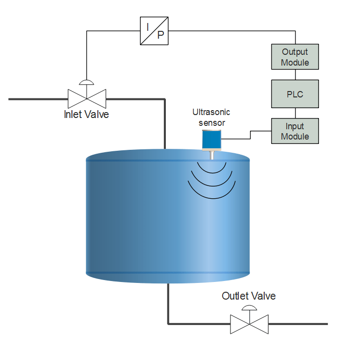
By using a control valve which is operated with standard pneumatic signal 3-15psi, level of a tank is to be maintained. Implement automation of this tank level system in PLC using Ladder Diagram programming language.
Problem Diagram
Problem Solution
- To measure the continuous level, Ultrasonic Sensor may be used.
- Rosemount 3100 series Ultrasonic Level Transmitters can be used to measure the level of the tank.
- Range of these transmitters is 9-11m.
- Output of these transmitters is in standard electrical signal 4-20mA. Convert this standard signal into digital signal by connecting level transmitter to Analog Input Module of PLC.
- Calibrate the transmitter and set output such that it gives 4mA when tank is empty and 20mA when tank is full. Convert this data in accordance to level in Centimeters.
- This gives output such as 0000h when input is 4mA and FFFFh when output is 20mA. Determine the level of tank to be maintained. Convert preset value to be the maximum output that means if the level to be maintained is 370cm, then convert value such that output is FFFFh when level is 370cm.
- At low level, valve must be fully open, so air to close valve is used here to maintain the inlet flow.
Program
Here is PLC program to Maintain Level of a Tank, along with program explanation and run time test cases.
List of Inputs and Outputs
 I:1/0	= Start						   (Input)
 I:1/1	= Stop						   (Input)
 O:2/0	= Latching Coil					   (Output)
 DIV	= Division block			           (Compute)
 MUL	= Multiplication	block			   (Compute)
 MOV	= Move instruction to move data	    		   (Logical)
 N7:0	= Input from transmitter in Hex form		   (Register)
 N7:2	= Storing conversion FFFFh into equivalent 400cms  (Register)
 N7:3	= Conversion of preset cms into equivalent hex	   (Register)
 O:3	= Output to which I-P converter is connected	   (Output)
Ladder diagram to maintain the level of a tank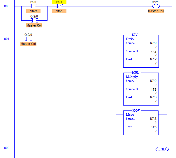
advertisement
advertisement
Program Description
- RUNG000 is a latching rung to operate the system through Master Start and Stop PB.
- RUNG001 comprises all the conversion needed to control level of the tank.
- Output of transmitter is in current signals which is 4-20mA.
- When output is 4mA, Analog Input Module converts it into 16bit equivalent hex numbers. Hence when input to Analog module is 4mA, it stores 0000h into register and when 20mA, it stores FFFFh into register. Here register N7:0.
- Let’s say here height of the tank is 4m or 400cm. By converting it into equivalent hex, change in value per centimeter is 164.
- Value of N7:0 is then multiplied with 173 because when Level reaches 380cm, output is 62259 in decimal. So when output at 380cm is multiplied with 173, we get full FFFFh at N7:2 to operate valve to fully close.
- This multiplication is stored into N7:2 register. Digital to Analog conversion of value stored in N7:2 is performed inside the processor and equivalent mA current is received from terminal O:3.
- Current to Pneumatic converter then converts current signals into equivalent 3-15psi pneumatic signal and adjusts valve opening.
Runtime Test Cases
Input	        Output  	Valve percentage open
N7:0 = 0000h	O:3 = 0000h	Valve fully open
N7:0 = F333h	O:3 = FFFFh	Valve fully closed
N7:0 = 7999h	O:3 = 7FFFh	Valve 50% open
Sanfoundry Global Education & Learning Series – PLC Algorithms.
To practice all PLC programs, here is complete set of 100+ PLC Problems and Solutions.
