This is a PLC Program to Implement BCD to Excess-3 Code Conversion.
Problem Description
Implementing BCD to Excess-3 code conversion in PLC using Ladder Diagram programming language.
Problem Solution
- Excess-3 code can be derived from BCD code by adding 3 to each number.
- For example, Decimal number 12 is represented as 0001 0010 in BCD. If we add 3 that is to add 0011 0011 then the corresponding Excess-3 code is 0100 0101.
- Write the truth table relating BCD and Excess-3.
- Write Karnaugh-Map for each output and obtain simplified expression.
- Implement BCD to Excess-3 code conversion circuit using Logic Gates.
- Implement Logic Gates’ circuit in PLC using Ladder Diagram programming language.
Truth Table relating BCD and Excess-3 codes
Decimal	BCD inputs	                Excess-3 Code outputs
	B3	B2	B1	B0	E3	E2	E1	E0
0	0	0	0	0	0	0	1	1
1	0	0	0	1	0	1	0	0
2	0	0	1	0	0	1	0	1
3	0	0	1	1	0	1	1	0
4	0	1	0	0	0	1	1	1
5	0	1	0	1	1	0	0	0
6	0	1	1	0	1	0	0	1
7	0	1	1	1	1	0	1	0
8	1	0	0	0	1	0	1	1
9	1	0	0	1	1	1	0	0
Boolean expression for each Excess-3 code bits
 E3= m(5, 6, 7, 8, 9)
 E2= m(1, 2, 3, 4, 9)
 E1= m(0, 3, 4, 6, 7, 8)
 E0= m(0, 2, 4, 6, 8)
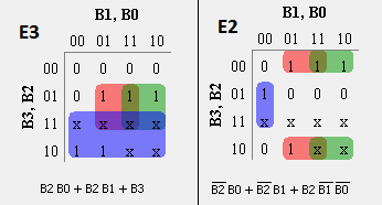
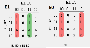
Karnaugh-Map solution for each output
advertisement
advertisement
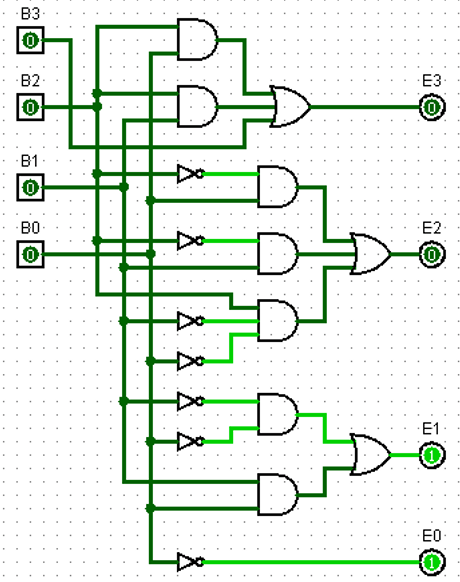
Realizing code conversion using Logic Gates
PLC Program
Here is PLC program to Implement BCD to Excess-3 Code Conversion, along with program explanation and run time test cases.
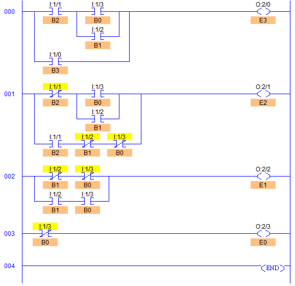
List of Inputs and Outputs
 B3=		I:1/0	(Input)
 B2=		I:1/1	(Input)
 B1=		I:1/2	(Input)
 B0=		I:1/3	(Input)
 E3=		O:2/0	(Output)
 E2=		O:2/1	(Output)
 E1=		O:2/2	(Output)
 E0=		O:2/3	(Output)
Ladder Diagram to obtain Excess-3 code output
Program Description
- In RUNG000 as we can see, to perform B0+B1, both inputs are connected in parallel to each other and this parallel connection is in series with B2 (I:1/1) to obtain B2(B0 + B1) as in simplified expression. To finally obtain output E3 (O:0/0), B3 (I:1/0) is connected in parallel to entire term B2(B0 + B1) that is I:1/1 (I:1/3 + I:1/2).
- Similarly in all rungs, XIO and XIC are connected according to simplified expression.
- RUNG002 and RUNG003, it can be noted in the Circuit Diagram that XIO connections of B0 and B1 are made in order to set E0 and E1 to 1 which makes E3E2E1E0 = 0011 (03).
Runtime test Cases
Decimal	BCD inputs              	Excess-3 Outputs
	B3	B2	B1	B0	E3	E2	E1	E0
0	0	0	0	0	0	0	1	1
1	0	0	0	1	0	1	0	0
2	0	0	1	0	0	1	0	1
3	0	0	1	1	0	1	1	0
4	0	1	0	0	0	1	1	1
5	0	1	0	1	1	0	0	0
6	0	1	1	0	1	0	0	1
7	0	1	1	1	1	0	1	0
8	1	0	0	0	1	0	1	1
9	1	0	0	1	1	1	0	0
Sanfoundry Global Education & Learning Series – PLC Algorithms.
advertisement
To practice all PLC programs, here is complete set of 100+ PLC Problems and Solutions.
advertisement
