This is a PLC Program to Count and Pack Parts from Conveyor.
Problem Description
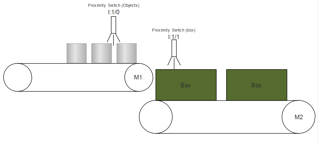
Objects are moving on a conveyor belt 1. When an empty box is detected, conveyor belt starts and 5pcs are packed in a box. When box is filled, it is carried to the storage area via conveyor belt 2. Implement automation of this process in PLC using Ladder Diagram programming language.
Problem Diagram
Problem Solution
- Use proximity switches to detect moving objects on the conveyor belt 1 and to detect an empty box on conveyor belt 2.
- Use counter to count number of objects to be packed.
- Use timer such that when 5pcs are detected, conveyor runs for a while and stops when 5th object is finally collected in the box. Assume time by calculating conveyor belt speed.
- When number of parts to be packed are detected timer is activated. When timer is over, it stops the conveyor until next empty box is detected.
- Assuming time taken by the last 5th object is 2secs to be collected.
PLC Program
Here is PLC program to Count and Pack Parts from Conveyor, along with program explanation and run time test cases.
List of Inputs and Outputs
 I:1/14	= Start 			(Input)
 I:1/15	= Stop 				(Input)
 B3:0/0	= Latching Bit 			(Bit)
 B3:0/1	= Latching Motor 1 bit 		(Bit)
 I:1/0	= Part detection 		(Input)
 I:1:1	= Box detection 		(Input)
 O:2/0	= Conveyor Belt 1 		(Output)
 O:2/1	= Conveyo2 Belt 2 		(Output)
 C5:0	= Part counter 			(Counter)
 T4:0	= Timer to stop conveyor	(Timer)
Ladder Diagram to count and pack parts
advertisement
advertisement
Program Description
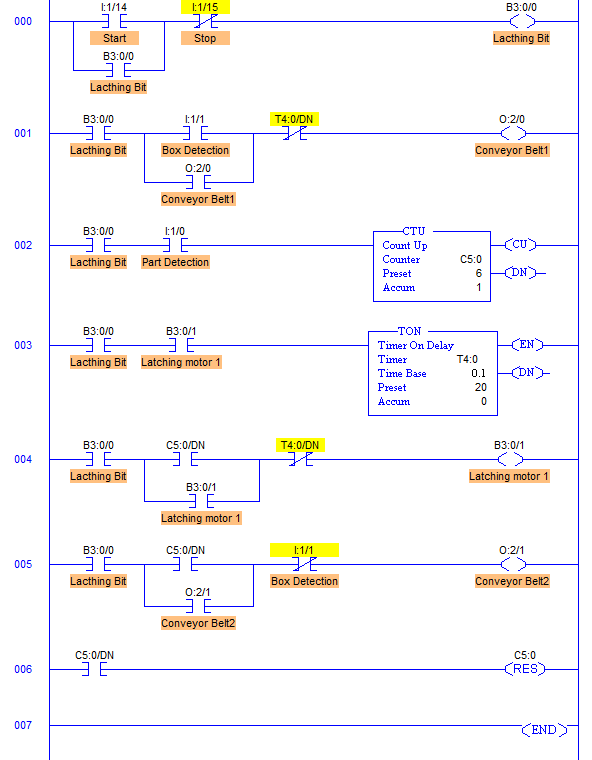
- RUNG000 is for master start and stop the process.
- RUNG001 is for controlling Conveyor Belt 1 motor M1 which is operated by Box Detection proximity switch. When the process is started and empty box is detected by Proximity having address of I:1/1, power supply to the motor of Conveyor Belt 1 is given. This drives the Motor M1 moving objects on the conveyor belt 1.
- Every time a part is detected by the I:1/1 Part detector, Counter C5:0 is incremented by 1. Counter has a preset value of 6. Here that means when total 5 parts are detected, counter done bit C5:0/DN is set to 1.
- When C5:0/DN bit is set, timer T4:0 is activated for 2secs which is an assumption that the part will take approximately 2secs to fall into the box after it is detected by the Pat Detector proximity switch I:1/0.
- Counter is immediately reset when C5:0/DN goes true. So one shot is generated by C5:0/DN bit. It latches the Latching Motor1 bit before it goes false.
- Conveyor Belt 2 motor M2 (O:2/1) is operated when counter value reaches to 6 that is when total 5 parts are detected. And it is stopped when an empty box is detected again.
- And the process is repeated.
- Important thing to note here is that Counter Preset is set 6 that is because when the counter is reset, the value is the accumulator is set to 1 because of latching bit.
Runtime Test Cases
Inputs	                Output	              Physical Elements
I:1/1 = 1	        O:2/0 = 1, O:2/1 = 0  Start Conveyor1, Stop Conveyor2
I:1/0 = 1(Momentarily)	C5:0.ACC = +1	      Part is detected, Increment Counter
C5:0.ACC = 6            T4:0.EN = 1	      Enable Timer T4:0, Reset Counter
T4:0/DN = 1             O:2/1 = 1	      Start Conveyor2, Stop Conveyor1
Sanfoundry Global Education & Learning Series – PLC Algorithms.
To practice all PLC programs, here is complete set of 100+ PLC Problems and Solutions.

