This is a PLC Program to Operate Light as an Emergency Signal.
Problem Description
Boiler is being operated and monitored using a PLC. Temperature set point of boiler is 600°C and maximum temperature limit is 610°C. If temperature rises above its maximum limit. Hooter and emergency lights are activated in order to inform operator. Implement this in PLC using Ladder Diagram programming language.
Problem Solution
- There are two methods to solve this problem. One is by using stack operation and the other one is by using sequencer output method.
- Sequencer output method is best suited for this problem since very less configuration is needed and program length is also reduced.
- In this method, we need to assign SQO instruction by configuring all the parameters given in the instruction.
- Alarm signal must be continuous until operator turns it off manually.
- Sequencing of Lights and Hooter is done here by using SQO Sequential Output to operate lights and hooter.
- Set timer to activate and deactivate hooter and lights or to be précised, change sequence of output.
- Let’s say, these both outputs are energized for 1sec and de-energized for next 1sec.
- In sequencer output, the start position is all zeros. So to start the actual function of output sequence, Position 1 is determined as starting sequence while programming.
PLC Program
Here is PLC program to Operate Light as an Emergency Signal, along with program explanation and run time test cases.
List of Inputs and Outputs
 I:1/0	= Start 				(Input)
 I:1/1	= Stop					(Input)
 O:2/0	= Master Coil				(Output)
 T4:0	= Timer to update output sequence	(Timer)
 SQO	= Sequencer output			(Sequencer)
 O:2/0	= Emergency Red Light (From O:2)	(Output)
 O:2/1	= Hooter	      (From O:2)	(Output)
 R6:0	= Control Register			(Register)
 N7:0	= File register				(Register)
-(RES)- = Reset outputs and Position of SQO	(Logical)
Ladder Diagram to control light as emergency signal with hooter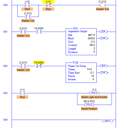
Program Description
- File; #N7:0 and File length is 2, hence output sequence is varied from N7:0 and N7:1 with each input.
- Destination is set to O:2 hence with each transition, N7:0 and N7:1 are moved to O:2 with masking.
- O:2/0 and O:2/1 are used as the output address to Emergency Light and a Hooter, hence Mask has value 0003h which means data flow of N7:0/0, N7:0/1, N7:1/0 and N7:1/1 are passed to O:2/0 and O:2/1, and remaining bits are blocked.
- Control parameters are assigned to register R6:0.
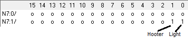
- Sequence of Light and Hooter to be operated are stored in the registers N7:0 and N7:1 as following.
advertisement
advertisement
- Time base is set to 1sec, hence after every 1sec, output sequence is changed to its next register pattern output which is then transferred to O:2 and O:2/0-O:2/1 are energized accordingly.
- As we can see, N7:1 and N7:2 have the exact opposite bit pattern. So, these bits are set to 1 for 1 cycle and reset for the next cycle. These bits are used to operate Hooter and a Light.
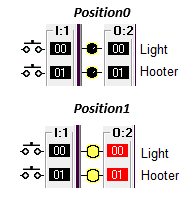
- So when I:1/0 is pressed, during position 0, outputs and remain in OFF condition and are energized when SQO is at position 1.
- When Stop PB with address I:1/1 is pressed, Position is reset to 0 and all the outputs are de-energized.
Runtime Test Cases
Sanfoundry Global Education & Learning Series – PLC Algorithms.
To practice all PLC programs, here is complete set of 100+ PLC Problems and Solutions.
