This is a PLC Program to Simply Latch and Unlatch an Output.
Problem Description
Perform Latching and Unlatching of an output (Pilot Light, Motor, Solenoid Coil etc.).
Problem Solution
- Almost all the PLCs come along with Latch and Unlatch instructions inbuilt.
- They all must be used in two rungs in order to operate an output.
- Different manufactures have provided different names to these Instructions.
- Allen Bradley PLCs have -(L)- for Latching and -(U)- for Unlatching instructions, Siemens PLCs have (S) for Set and (R) for Reset instructions. Similarly, Omron PLCs have KEEP instruction for latching.
- All these instructions perform the same task of Latching when one input is pressed and Unlatching when another input is pressed.
- Two Push Buttons are required to perform this task.
- Any output to be Latched is required which is connected physically as an output device.
PLC Program
Here is PLC program to Simply Latch and Unlatch an Output, along with program explanation and run time test cases.
List of Inputs & Outputs
 SW1 = Switch1			I:1/0 & 0.00	(Input to Latch)
 SW2 = Switch2			I:1/1 & 0.01	(Input to Unlatch)
 Bit stored to latch		100.00		(Stored Bit Address)
 Output				O:2/0 & 200.00	(Output Light)
Ladder Diagram to obtain output Latching and Unlatching in Allen Bradley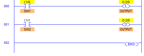
Ladder Diagram to obtain output Latching and Unlatching in Omron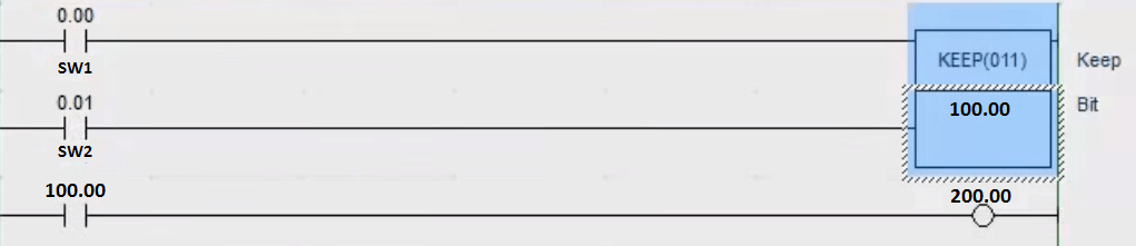
Program Description
- first figure shows how programming of Latching and Unlatching is done in Allen Bradley PLCs and 2nd shows how Latching and Unlatching is done in Omron PLCs.
- Siemens PLCs and Allen Bradley have similar instruction types. The only difference is that Latch is replaced by Set and Unlatch is replaced by Reset. Addressing varies as well.
- In first figure, when SW1 is pressed momentarily, the Output goes True even if the input from SW1 is withdrawn, this happens because whenever the input SW1 is pressed, O:2/0 stores the bit and output remains True even if from Switch SW1 is withdrawn.
- This output goes False only when the switch SW2 is pressed resetting the O:2/0 bit which Unlatches the Output.
- In 2nd figure, as we can see, Omron PLCs use KEEP instruction which is a single rung instruction comprising of two different inputs, one to set the bit and other to reset the bit. Latching and Unlatching is here done by KEEPing the bit and accordingly Output is Latched and Unlatched.
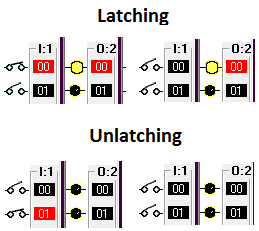
Runtime Test Cases
advertisement
advertisement
Sanfoundry Global Education & Learning Series – PLC Algorithms.
To practice all PLC programs, here is complete set of 100+ PLC Problems and Solutions.
