This is a PLC Program to Implement a Combinational Logic Circuit (2).
A circuit has 4 inputs (A, B, C, and D) and 2 outputs (Y1, Y2). One of the outputs is high when majority of inputs are high. The second output is high when all inputs are of same type. Design the combinational circuit and implement it in PLC using Ladder Diagram programming language.
Y1=1 if majority of inputs are high.
Y2=1 if A=B=C=D.
- To solve this problem, first the table showing ON state of Y1 and Y2 is created. (When Y1 or Y2 is 1).
- According to the table designed, Y1 and Y2 both will have different equations, Y1 when input binary number is 5 or less than 5 and Y2 when input is 9 or more than 9.
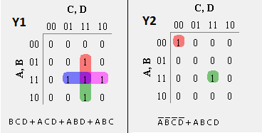
- To obtain these equations, Karnaugh-Map method is again used.
- By solving output expressions, we obtained minimized form of equation which is then applied into Ladder Diagram.
Output table and Karnaugh-Map method to solve Y1 and Y2 equations.
Binary Inputs	                Outputs
A	B	C	D	Y1	Y2
0	0	0	0	0	1
0	0	0	1	0	0
0	0	1	0	0	0
0	0	1	1	0	0
0	1	0	0	0	0
0	1	0	1	0	0
0	1	1	0	0	0
0	1	1	1	1	0
1	0	0	0	0	0
1	0	0	1	0	0
1	0	1	0	0	0
1	0	1	1	1	0
1	1	0	0	0	0
1	1	0	1	1	0
1	1	1	0	1	0
1	1	1	1	1	1
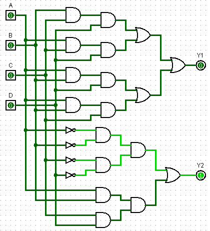
Combinational Circuit for outputs expressed using logic gates
Here is PLC program to Implement a Combinational Logic Circuit , along with program explanation and run time test cases.
List of Inputs and Outputs,
A =			I:1/0	(Input)
B =			I:1/1	(Input)
C =			I:1/2	(Input)
D =			I:1/3	(Input)
Y1=			O:2/0	(Output)
Y2=			O:2/1	(Output)
Ladder Diagram to obtain combinational logic circuit outputs
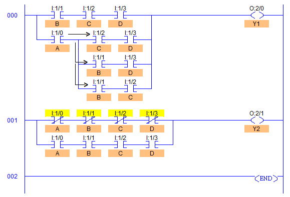
- RUNG000 is developed to obtain output Y1 (O:2/0) according to the condition that when majority of inputs are high, output Y1 is high.
- RUNG001 is developed to obtain output Y1 (O:2/1) according to the condition that when A=B=C=D=0/1, output Y2 is high.
- As we can see in RUNG001, in order to get Y2, output identical to multi-input EX-NOR gate is obtained by solving expressions using Karnaugh-Map method.
- Output Y1 is high whenever any of the three inputs are high irrespective of the remaining one bit. Hence in total number of combination, only these 4 combinations ABC, ABD, BCD and ACD are there which have 3 or more than 3 inputs in high state.
- Hence this can be accomplished by connecting these combinations in series with parallel to each other as shown in Ladder Diagram above.
- Output Y2 is high in only two conditions, whenever all the inputs are Set to 1 or are Reset to 0. Hence this can be accomplished by connecting ‘XIO connections of ABCD in series’ parallel to ‘XIC connections of ABCD in series’ inputs.
Binary Inputs                 No. of    Same
                           Inputs HIGH  Inputs  Outputs
A	B	C	D			Y1	Y2
0	0	0	0	0	Yes	0	1
0	0	0	1	1	No	0	0
0	0	1	0	1	No	0	0
0	0	1	1	2	No	0	0
0	1	0	0	1	No	0	0
0	1	0	1	2	No	0	0
0	1	1	0	2	No	0	0
0	1	1	1	3	No	1	0
1	0	0	0	1	No	0	0
1	0	0	1	2	No	0	0
1	0	1	0	2	No	0	0
1	0	1	1	3	No	1	0
1	1	0	0	2	No	0	0
1	1	0	1	3	No	1	0
1	1	1	0	3	No	1	0
1	1	1	1	4	Yes	1	1
Sanfoundry Global Education & Learning Series – PLC Algorithms.
To practice all PLC programs, here is complete set of 100+ PLC Problems and Solutions.
If you find any mistake above, kindly email to [email protected]