This is a PLC Program to Measure the Scan Cycle of PLC.
Problem Description
Measure the scan cycle of a PLC using Ladder Diagram programming language.
Problem Solution
- Use toggling output which toggles every time scan cycle is completed.
- This can be done by connecting an XIO contact and an output in series with the same addresses.
- Use this toggling bit as an input to up counter to increment number of times the bit toggles.
- Use 1sec timer to stop the counter from counting, because the bit is toggling continuously and it might unnecessarily increment counter value even after 1sec is over.
- Reset counter to clear the accumulator data to measure the scan cycle again.
PLC Program
Here is PLC program to Measure the Scan Cycle of PLC, along with program explanation and run time test cases.
List of Inputs and Outputs
 O:2/0	 = Toggling output			(Output)
 B3:0/0	 = Latching Bit				(Bit)
 I:1/0	 = Start measurement PB		        (Input)
 I:1/1	 = Reset Counter PB     		(Input)
 T4:1	 = 1sec time delay			(Timer)
 C5:0	 = Up counter to increment each toggle	(Counter)
 O:6	 = Display address			(Output)
 TOD	 = Hex to BCD conversion		(Compute)
 T4:0/DN = Stop counting			(Timer)
 -(RES)- = Reset Counter coil			(Output)
Ladder Diagram to measure scan cycle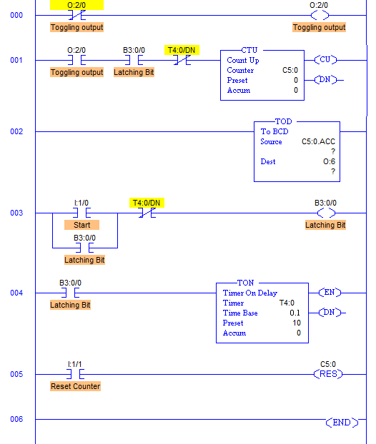
Program Description
- When this program is Run, during first scan cycle, output image table memory bit O:2/0 is detected as 0 hence it allows the current through RUNG000 and updates output image table memory bit O:2/0 to 1. During the second scan cycle, O:2/0 is detected 1, hence it blocks current flow through the RUNG000 and output image table memory bit O:2/0 is reset to 0. This process continues till it is stopped manually.
- This toggling of a memory bit is fed to Up Counter with address C5:0 and every time the bit toggles, counter is incremented by 1.
- Scan cycle is defined as the Scans per second (Scans/Sec).
- To fulfill this definition requirement, 1sec timer is added in this program to stop the incrementing of Counter after 1sec when Star PB is pressed which is done by placing XIO of T4:0/DN in series with Up Counter CTU.
- Accumulator value is converted into BCD and fed to Display with address O:6.
Runtime Test Cases
Average value of scan cycle in LogixPro simulation software was detected 16 when it was set to Minimum Scans.
Average value of scan cycle in LogixPro simulation software was detected 235 when it was set to Maximum Scans.
advertisement
advertisement
Sanfoundry Global Education & Learning Series – PLC Algorithms.
To practice all PLC programs, here is complete set of 100+ PLC Problems and Solutions.
