This is a PLC Program to Drain Same Products from 2 Tanks.
Problem Description
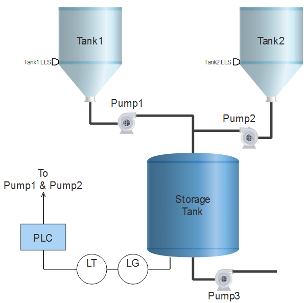
Two tanks have same products filled. Draining from these depends on the requirement from the storage tank. Implement automation of this draining system in PLC using Ladder Diagram programming language
Problem Diagram
Diagram showing draining through pumps
Problem Solution
- Level gauge is used to measure level of the storage tank continuously
- Level gauge is connected with Level Transmitter which converts corresponding level output in 4-20mA equivalent.
- Analog I/O Modules are chosen to deal with Analog signals.
- Centrifugal pumps are used to drain material from both the tanks at the same time.
- Two low level switches are used to detect low level of tanks 1 and 2 which turns Pumps OFF when low level is reached.
- Height of storage tank is 5meters that is 500cm and the level which is to be maintained is 470cm.
- Calculate necessary conversions and use registers to store data and to do arithmetic operations.
PLC Program
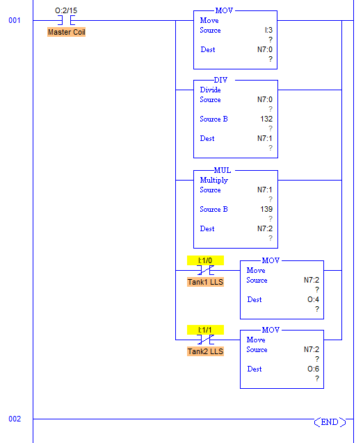
Here is PLC program to Drain Same Products from 2 Tanks, along with program explanation and run time test cases.
List of Inputs and Outputs
 I:1/14	= Start							(Input)
 I:1/15	= Stop							(Input)
 O:2/15	= Mater Coil						(Output)
 I:1/0	= LLS of Tank1						(Input)
 I:1/1	= LLS of Tank2						(Input)
 O:4	= Output to I-V converter of Pump1			(Output)
 O:6	= Output to I-V converter of Pump2			(Output)
 I:3	= Input to which transmitter is connected		(Input)
 N7:0	= Register to store input data				(Register)
 N7:1	= answer of division by value change per centimeter	(Register)
 N7:2	= Multiplication answer					(Register)
Ladder diagram to control draining of liquid from the tank
advertisement
advertisement
Program Description
- RUNG001 comprises all the conversion needed to control pumps.
- Output of transmitter is in current signals which is 4-20mA.
- When output is 4mA, Analog Input Module converts it into 16bit equivalent hex numbers. Hence when input at I:3 to Analog module is 4mA, it moves 0000h into register and when 20mA, it moves FFFFh into register. Here register N7:0.
- Here height of the tank is 5m or 500cm. By converting it into equivalent hex, change in value per centimeter is 132.
- Value of N7:0 is then multiplied with 139 because when Level reaches 470cm, output is F0C0h. So when output at 470cm is multiplied with 139, we get full FFFFh at N7:2 to operate pumps in full speed.
- This multiplication is stored into N7:2 register. Digital to Analog conversion of value stored in N7:2 is performed inside the processor and equivalent mA current is received from terminal O:4 and O:6.
- Current to Voltage converter then converts current signals into voltage signal and adjusts motor speed.
- Two pumps are used here hence speed of response is very good and smooth operation is achieved.
Reset operation to turn off Pumps when low level is detected
- Both tanks have a Low Level switch at the bottom. When there is no material in the tank or very less material is present, pump should not run in order to prevent it from failure. Limit switch with address I:1/0 is for tank1 and I:1/1 is for tank2.
Runtime Test Cases
Inputs	        Outputs         	Physical Elements
I:3 = F258h	O:4 = O:6 = 0000h	Pump1 and Pump2 are off
I:3 = 792Ch	O:4 = O:6 = 8000h	Pump1 and Pump2 = 4000RPM
I:3 = 50C8h	O:4 = O:6 = 5474h	Pump1 and Pump2 = 2640RPM
I:1/0 = 1	O:4 = 0000h     	Pump1 off
I:1/1 = 1	O:6 = 0000h	        Pump2 off
Sanfoundry Global Education & Learning Series – PLC Algorithms.
To practice all PLC programs, here is complete set of 100+ PLC Problems and Solutions.
