This is a PLC Program to Control Mixing in a Tank.
Problem Description
Material A and Material B are collected in a tank. These materials are mixed for a while. Mixed product is then drained out through Outlet valve. Implement this in PLC using Ladder Logic programming language.
Problem Diagram
Diagram of a mixing tank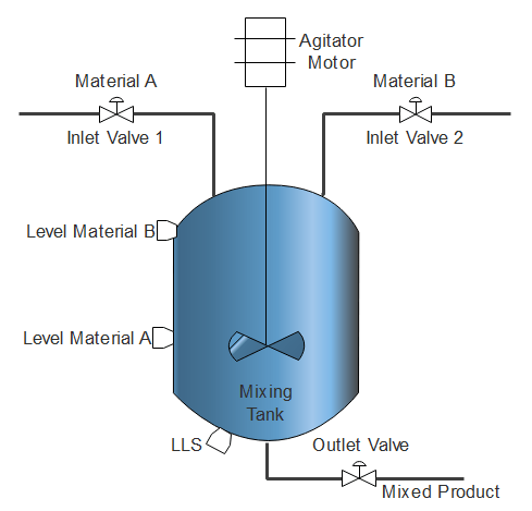
Problem Solution
- To detect level of Material A and Material B, two separate level switches are used.
- And to detect low level, one more level switch is used at the bottom of the tank.
- These give output in digital terms that is when corresponding levels are detected.
- To control level of this system, Single Acting Piston valve can be used which has two states, either fully open or fully close.
- To control mixing, agitator is used which is connected with Motor shaft.
- Particular time delay is generate to mix the materials for a definite time.
- Control inlet valves on the basis of Level Material switches A and B.
- Outlet valve is then operated to drain the mixed product.
PLC Program
Here is PLC program to Control Mixing in a Tank, along with program explanation and run time test cases.
List of Inputs and Outputs
 I:1/14	= Start 				(Input)
 I:1/15	= Stop					(Input)
 B3:0/0	= Master Coil Bit			(Bit)
 I:1/0	= Level of Material B			(Input)
 I:1/1	= Level of Material A			(Input)
 I:1/2	= Low Level Switch (detects empty tank)	(Input)
 O:2/0	= Inlet Valve 1 (Material A Feed)	(Output)
 O:2/1	= Inlet Valve 2 (Material B Feed)	(Output)
 O:2/2	= Agitator Motor (Mixing)		(Output)
 O:2/3	= Outlet Valve (Product Outlet)		(Output)
 T4:0	= Time to mix Materials			(Timer)
Ladder Diagram to control mixing in the tank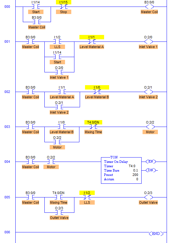
advertisement
advertisement
Program Description
- RUNG000 contain master start/stop with address of Start PB I:1/14 and Stop PB I:1/15.
- RUNG001 is to operate Inlet Valve of Material A with address O:2/0. It is operated when Low Level of the tank is detected by Level Low Switch I:1/2. And it is closed when Level Material A is detected by a switch with address I:1/1. Start PB is also connected in parallel with the LLS, it is done so that when LLS or level of Material A is not detected, Inlet Valve is operated by Start PB.
- RUNG002 is to operate Inlet Valve of Material B with address O:2/1. It is opened when Material A is filled to its desired level (Level Material A). In other words, Valve of Material B is opened when Level of Material A is detected by I:1/1 and it is closed when Level of Material B is detected or Tank is full.
- RUNG003 & RUNG004 operates Agitator Motor with address O:2/2. When the tank is full with Material A and B, Level High (Level Material B) is detected. This detection energizes O:2/2 and enables ON timer with address T4:0. Agitator Motor is connected to the address O:2/2. So when O:2/2 energizes, Motor Agitator starts the mixing process and mixes Material A and B for 20secs which is a preset of Timer ON. When Pre = Acc, T4;0/DN bit goes high turning off the agitator motor.
- RUNG005 is for Outlet Valve with address O:2/3. It is operated when the entire mixing process is completed that is when Pre= Acc = 20secs. And this is closed when LLS is again detected.
- Timer On is set to auto reset mode.
Runtime Test Cases
Inputs	                Outputs	      Physical Elements
I:1/2 = 1	        O:2/0 = 1     Open Inlet Valve 1
I:1/2 = 0 & I:1/1 = 0	O:2/0 = 1     Open Inlet Valve 1
I:1/1 = 1	        O:2/0 = 0     Close Inlet Valve 1
I:1/1 = 1	        O:2/1 = 1     Open Inlet valve 2
I:1/0 = 1        	O:2/1 = 0     Close Inlet Valve 2
I:1/0 = 1	        O:2/2 = 1     Run Agitator Motor
T4:0/DN = 1	        O:2/2 = 0     Stop Agitator Motor
T4:0/DN = 1	        O:2/3 = 1     Open Outlet Valve
I:1/2 = 1	        O:2/3 = 0     Close Outlet Valve
Sanfoundry Global Education & Learning Series – PLC Algorithms.
To practice all PLC programs, here is complete set of 100+ PLC Problems and Solutions.
