This is a PLC Program to Implement 8 to 3 Encoder.
Problem Description
Implement 8 to 3 line encoder in PLC using Ladder Diagram programming language.
Problem Solution
- It has 8 inputs I0 to I7 and 3 outputs Q0 to Q3.
- These inputs I0 to I7 determines which output should be active.
- If I2 is true that means input 2 is selected. Output of 2 is 011 in binary hence outputs Q1 and Q2 will go high and Q0 remains in its low state.
- It does not need K-map and simplification so one step is eliminated to create Ladder Logic Diagram.
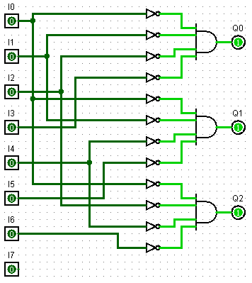
- Realize the 8 to 3 line encoder using Logic Gates.
Truth Table can be written as given below.
Inputs	Outputs
	Q0	Q1	Q2
I0=1	0	0	0
I1=0	0	0	1
I2=1	0	1	0
I3=1	0	1	1
I4=1	1	0	0
I5=1	1	0	1
I6=1	1	1	0
I7=1	1	1	1
Realization of 3 to 8 line decoder using Logic Gates
PLC Program
Here is PLC program to Implement 8 to 3 Encoder, along with program explanation and run time test cases.
advertisement
advertisement
List of Inputs and Outputs
 I0=		I:1/0	(Input)
 I1=		I:1/1	(Input)
 I2=		I:1/2	(Input)
 I3=		I:1/3	(Input)
 I4=		I:1/4	(Input)
 I5=		I:1/5	(Input)
 I6=		I:1/6	(Input)
 I7=		I:1/7	(Input)
 Q0=		O:2/0	(Output)
 Q1=		O:2/1	(Output)
 Q2=		O:2/2	(Output)
Ladder Diagram for 8 to 3 line encoder
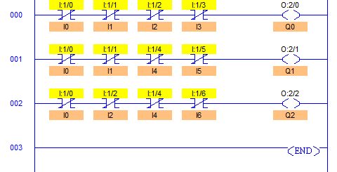
Program Description
- As we can see that Q0 O:2/0 is active whenever I4 I:1/4 to I7 I:1/7 inputs are pressed because in 3bit addresses, 1st bit goes high only when “input > integer 3 (011)”.
- Similarly Output Q1 O:2/1 goes high in two conditions, 1 < Input < 4 and 5 < Input < 8.
- And Output Q2 O:2/2 goes high whenever Odd number is given in input, i.e. here 1, 3, 5, 7.
- So basically in I7 I:1/7, all the inputs go true and in I0 I:1/0, all the outputs remain false.
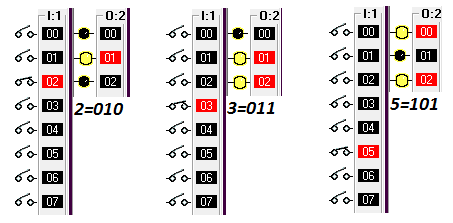
Runtime Test Cases
Inputs	Outputs
	Q0	Q1	Q2
I0=1	0	0	0
I1=1	0	0	1
I2=1	0	1	0
I3=1	0	1	1
I4=1	1	0	0
I5=1	1	0	1
I6=1	1	1	0
I7=1	1	1	1
Sanfoundry Global Education & Learning Series – PLC Algorithms.
To practice all PLC programs, here is complete set of 100+ PLC Problems and Solutions.
advertisement
