This is a PLC Program to Operate Seven Segment Display.
Problem Description
Implement displaying 0-9 digits in 7 Segment LED Display interfacing with PLC using Ladder Diagram programming language.
Problem Solution
- 7 Segment LED Displays are also known as BCD to 7 Segment decoder.
- These displays are readily available or can be made easily organizing simple LEDs in the same structure as in actual display.
- Input to this display is BCD number which are decoded into digits 0 to 9.
- Connect this display with Output card of a PLC.
- Write a truth table to energize various outputs according to BCD input applied.
- This displays do not come with internal latches, we can latch inputs in PLC using either seal in contact or Latch-Unlatch instructions in Allen Bradley and Set-Reset instructions in Siemens PLCs.
- Use K-Map to obtain output equations.
- Implement this equations in Ladder Diagram format using AND and OR operations.
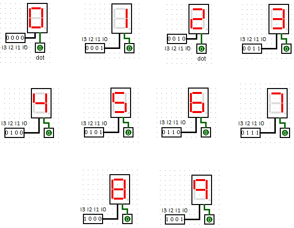
Truth Table of 7 Segment Display
Inputs	Outputs
	a b c d	e f g	Display
0000	1 1 1 1	1 1 0	0
0001	0 1 1 0	0 0 0	1
0010	1 1 0 1	1 0 1	2
0011	1 1 1 1	0 0 1	3
0100	0 1 1 0	0 1 1	4
0101	1 0 1 1	0 1 1	5
0110	1 0 1 1	1 1 1	6
0111	1 1 1 0	0 0 0	7
1000	1 1 1 1	1 1 1	8
1001	1 1 1 1	0 1 1	9
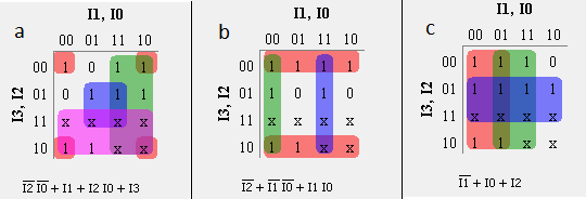
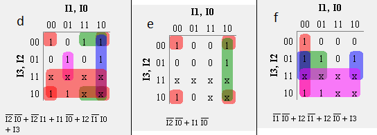
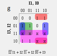
Simplified Boolean expressions to obtain a to g outputs using K-Map
PLC Program
Here is PLC program to Operate Seven Segment Display, along with program explanation and run time test cases.
advertisement
advertisement
List of Inputs and Outputs
I:1/0 to I:1/3	= I0 Input 0 to I3 Input 3 respectively.	(Input)
O:2/0 to O:2/6	= a to g respectively.				(Outputs)
Ladder Diagram for 7 segment display
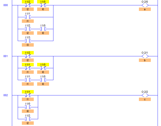
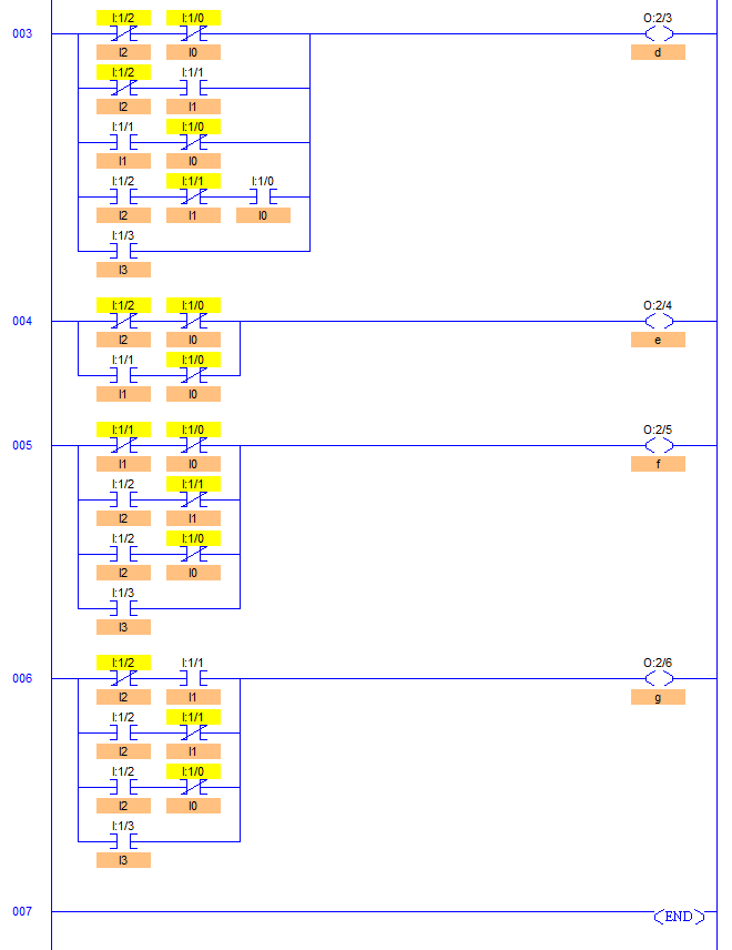
Program Description
- After performing K-Map simplification method, equations for all the 7 outputs are obtained.
- I:1/0 to I:1/3 are the inputs I0 to I3 respectively and O:2/0 to O:2/6 are the outputs ‘a’ to ‘g’ respectively.
- Output ‘a’ 0:2/0 energizes in 4 cases, when I2 and I0 are low, I1 is high, I0 and I2 are high or when I3 is high.
- Output ‘c’ O:2/2 energizes in 3 cases, when I1 is low, I0 is high, or when I2 is high.
- Similarly all the remaining outputs b, d, e, f and g are obtained.
- Simply this is a method to convert BCD inputs into Seven Segments to display 0-9 digits.
Separated by commas are different cases of outputs being energized.
Runtime Test Cases
Sanfoundry Global Education & Learning Series – PLC Algorithms.
To practice all PLC programs, here is complete set of 100+ PLC Problems and Solutions.
advertisement
