This is a PLC Program to Operate Screwing of Parts.
Problem Description
When a plate is placed, screws are to be fit at each corner of the plate. Use robotic arm to perform this action and implement automation of this in PLC using Ladder Diagram programming language.
Problem Diagram
Problem Solution
- Robotic arm used to perform this screwing action.
- Robotic arm used here is of 3-axis arm.
- Sequence of the arm is to be controlled.
- SQO instruction must be used in order to fulfill the requirements.
- Sequence to be followed is as given below.
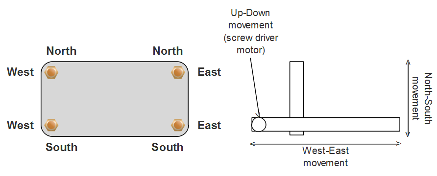
   1-  Arm is initially at South-East position
   2-  Arm lowers and screws.
   3-  Raise arm.
   4-  Move to West-South position
   5-  Arm lowers and screws.
   6-  Raise arm.
   7-  Move to West-North position.
   8-  Arm lowers and screws.
   9-  Raise arm.
   10- Move to North-East position.
   11- Arm lowers and screws.
   12- Raise arm.
   13- Move to South-East position.
PLC Program
Here is PLC program to Operate Screwing of Parts, along with program explanation and run time test cases.
List of Inputs and Outputs
 I:1/0		= Start PB			(Input)
 I:1/1		= Stop PB			(Input)
 I:1/2		= Part detector proximity	(Input)
 O:2/0		= Master coil			(Output)
 O:4/0		= Screwing Motor coil		(Output)
 O:4/1		= Down position		        (Output)
 O:4/2		= Up position			(Output)
 O:4/3		= West position			(Output)
 O:4/4		= East position			(Output)
 O:4/5		= South position		(Output)
 O:4/6		= North	position		(Output)
 N7:0		= File register			(Register)
 N7:1 to N7:13	= Sequence storing registers	(Register)
 R6:0		= Control Register		(Register)
Ladder diagram to perform Screwing of parts with robotized arm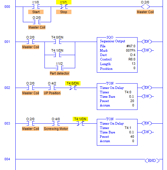
advertisement
advertisement
Program Description
- RUNG000 again here is for Master Start and Stop.
- File; #N7:0 and File length is 13, hence output sequence is varied from N7:0 to N7:12 with each input.
- Destination is set to O:4 hence with each transition, N7:0 to N7:12 are moved to O:4 with masking.
- O:4/0 to O:2/6 are used as the output address to Different positions and Motor coil, mask has value 007Fh which means data flow of N7:0/0…N7:12/0 to N7:0/5…N7:10/5 is passed and the remaining N7:0/7…N7:12/7 to N7:0/15…N7:12/15 are blocked.
- Control parameters are assigned to register R6:0.
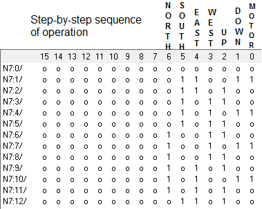
- Sequence of robotic arm to be operated are stored in the registers from N7:0 to N7:12 as following.
- When Start PB with assigned address I:1/0 is pressed, it energizes master coil O:2/0 and the system has started. You can connect this Master Coil to a Green LED which may indicate Run operation.
- When it is Run and a part is detected, it activates Sequential Output SQO and Position is changed to 1 from 0. This Sequential Output is also activated by T4:0/DN bit and T4:1/DN bit.
- We do not need robot arm to stay in the Up position for more than 2secs and screwing takes 4secs which is an estimation, hence two different timers T4:0 and T4:1 are assigned to do two different tasks.
- When the arm is in Down position and Motor runs, it means screwing is to be done. It takes approximately 4secs to screw one end. So whenever motor bit is activated, it takes 4secs to switch to next sequence.
- Similarly when the arm is in Up position, T4:0 is activated and Sequence is changed after 2secs.
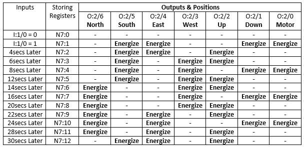
Runtime Test Cases
Sanfoundry Global Education & Learning Series – PLC Algorithms.
To practice all PLC programs, here is complete set of 100+ PLC Problems and Solutions.
