This is a PLC Program to Control Spray-Painting of Parts.
Problem Description
Control Spray-Painting operation in PLC using Ladder Diagram programming language.
Problem Diagram
Problem Solution
- Spray-Paining operation is similar to the bottle capping operation. The only difference is that Bottle Capping operation used timers while Spray-Paining operation do not require timers.
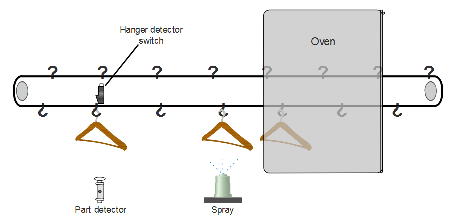
- Two limit switches are used, one to detect hangers and other to detect parts.
- Both are mounted exactly opposite to each other so that when part is not present, outputs are complement of each other.
- Bit shift register is used to spray parts.
- Oven is used to dry the parts after they are sprayed. This output is continuously ON and is not controlled.
PLC Program
Here is PLC program to Control Spray-Painting of Parts, along with program explanation and run time test cases.
List of Inputs and Outputs
 I:1/14	= Start					(Input)
 I:1/15	= Stop					(Input)
 I:1/0	= Limit switch (Hanger)			(Input)
 I:1/1	= Proximity (Part detection)		(Input)
 O:2/0	= Master coil / Run			(Output)
 O:2/1	= Oven					(Output)
 O:2/2	= Spray					(Output)
 BSL	= Bit shift left instruction		(Logical)
 B3:0	= Bit shift Register			(Register)
 B3:0/2	= Bit to energize capping machine	(Bit)
 R6:0	= Control register			(Register)
Ladder Diagram to operate Spray-Paining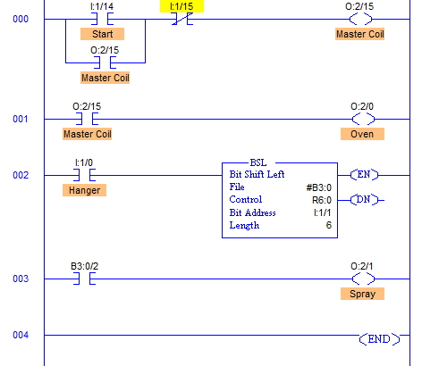
advertisement
advertisement
Program Description
- When Start PB is pressed, Oven with address O:2/0 is started.
- RUNG002 and RUNG003 are used to operate bit shift register and Spray with address O:2/1.
- I:1/0 and I:1/1 are mounted such that they are detected together. When Part is present, I:1/0 and I:1/1 both goes high setting bit B3:0/0. Shifting of this itself is operated by I:1/0 Hanger switch. So every time a hanger is detected, bit is shifted left.
- From proximity to capping machine, station distance is 3 steps. Hence bit B3:0/2 of B3:0 register operates spray solenoid.
- R6:0 is a control register where all the operations are handled.
Runtime Test Cases
Inputs	           Output	Physical Elements
I:1/14 = 1	   O:2/0 = 1	Turn ON oven
I:1/0 = 1	   BSL = 1	Shift bit to left
I:1/0 = I:1/1 = 1  B3:0/0 = 1	Set bit to operate Spray
B3:0/2 = 1         O:2/1 = 1	Activate spray
Sanfoundry Global Education & Learning Series – PLC Algorithms.
To practice all PLC programs, here is complete set of 100+ PLC Problems and Solutions.
