This is a PLC Program to Drive Motors Simultaneously with Interlocking.
Two Motors are running in a sequence one by one for a particular time. If the start button is pressed Motors run in sequence such that 1st Motor stays ON for 5secs and then 2nd Motor is turned ON and stays ON for 5secs. And the cycle is repeated until it is interrupted. While motors are running in the sequence, if one motor is running and the button of other motor is pressed, then the running Motor should stop and the other motor should run. Implement this logic in PLC using Ladder Diagram programming language.
- Define addresses of motors.
- Create latching seal in contact to start and stop the sequential operation.
- Use TON timer to generate a particular time delay, same or different.
- Use DN bit of first timer to energize 2nd motor coil and activate second timer.
- No need to use Reset coils, program will reset the timers itself after completion of each cycles.
- Use Parallel Start Motor contact to start one motor when other motor is running.
Here is PLC program to Drive Motors Simultaneously with Interlocking, along with program explanation and run time test cases.
List of Inputs and Outputs
 I:1/0	= Motor0 Start		(Input)
 I:1/1	= Motor2 Stop		(Input)
 I:1/2	= Master Start		(Input)
 I:1/3	= Master Stop		(Input)
 O:2/2	= Master Coil		(Output)
 O:2/0	= Motor0		(Output)
 T4:0 	= Motor0 Timer		(Timer)
 O:2/1	= Motor1		(Output)
 T4:1	= Motor1 Timer		(Timer)
Ladder Diagram for sequential operation of Motors with Interlocking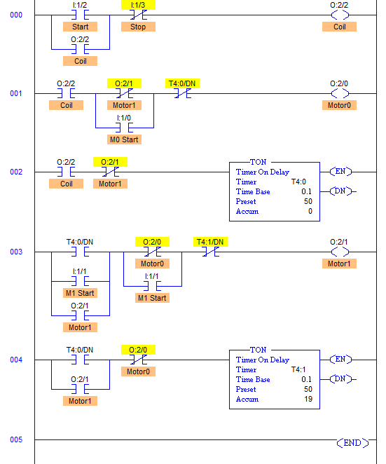
- RUNG000 is Latching coil for Master Start and Stop.
- RUNG001-RUNG002 and RUNG003-RUNG004 are arrangements to operate Motor0 O:2/0 and Motor1 O:2/1 respectively.
- When Start button is pressed momentarily, it latches the coil starting the energizing the output O:2/0, hence turning Motor0 ON.
- Timer T4:0 is used to run Motor0 for 5secs (Less because of simulation purpose).
- Similarly T4:1 is used to run Motor1 for 5secs.
- While Motor0 is running, and M1 Start I:1/1 is pressed, it stops the Motor0 (O:2/0 de-energizes) and Motor1 (O:2/1 energizes) starts and timer t4:1 is activated. And vice-versa.
- XIO contact of each motor’s output is used to turn other motor off by de-energizing other motor’s output which cuts off the current supply in the field.
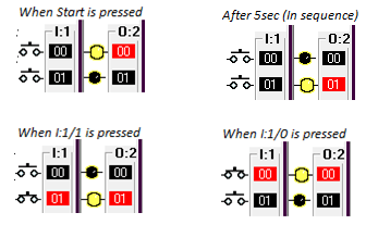
- LogixPro is used to Run Test Cases. You can also make this program in any simulation software and check all the cases.
- Worst cases were taken into account and solved.
Sanfoundry Global Education & Learning Series – PLC Algorithms.
To practice all PLC programs, here is complete set of 100+ PLC Problems and Solutions.
