This is a PLC Program for Oil and Water Separation Process.
Problem Description
Implement programming of Oil and Water separation process in PLC using Ladder Diagram programming language.
Problem Diagram
Problem Solution
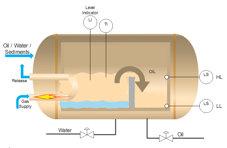
- Due to the gravitational force and different liquid density of Water and Oil, when water and oil both are present in the liquid, oil always reside on top of the liquid. By following this theory and making an arrangement shown in the diagram above, Oil and Water can be separated.
- However, this process does not completely remove water particles but only less than 10% of water contents are present after passing through this process.
- Level of the tank is monitored using level sensor. To control level of the system Inlet is controlled.
- To control the temperature of this system, ignition is to be controlled. Temperature sensor is used and gas supply flow is controlled to control temperature. Temperature set point here is 50 degree centigrade.
- Oil outlet is controlled by control valve which is operated by two level switches.
PLC Program & Program Description
Here is PLC program for Oil and Water Separation Process, along with program explanation and run time test cases.
List of Inputs and Outputs
 I:1/14		= Start						   (Input)
 I:1/15		= Stop						   (Input)
 O:2/15		= Master Coil					   (Output)
 I:3		= Level sensor output				   (Input)
 N7:0-N7:2	= Level monitoring and controlling registers	   (Registers)
 O:3		= Inlet controlling valve			   (Output)
 O:6		= Level Display					   (Output)
 I:1/1		= High level (Oil)				   (Input)
 I:1/0		= Low level (Oil)				   (Input)
 O:2/0		= Oil output valve (Single actuating)		   (Output)
 I:4		= Temperature output from sensor		   (Input)
 N7:3 to N7:5	= Temperature monitoring and controlling registers (Registers)
 O:5		= Gas supply controlling valve			   (Output)
 O:7		= Temperature Display				   (Output)
Ladder diagram to monitor and control Oil and Water separation process
advertisement
advertisement
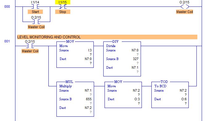
- RUNG000 is the master start and stop control rung.
- RUNG001 is for Level Monitoring and control of Oil and Water separation process tank.
- I:3 is an input where Level sensor is connected with. Height of the tank is 200cms. And we need to control the level till 100cm. hence output of the sensor is divided by 327 which means that per cm, input is added with 327.
- This data is further processed and multiplied by 655, because when output is 100cm, we have to throttle inlet valve to be fully closed. So when output is 100cm in N7:1 register, it is multiplied by 655 and the full throttling is received at O:3 which is connected to Inlet valve through I-P converter.
- N7:1 stores the level of the tank which is moved to O:6 (Display address) through Decimal to BCD converter.
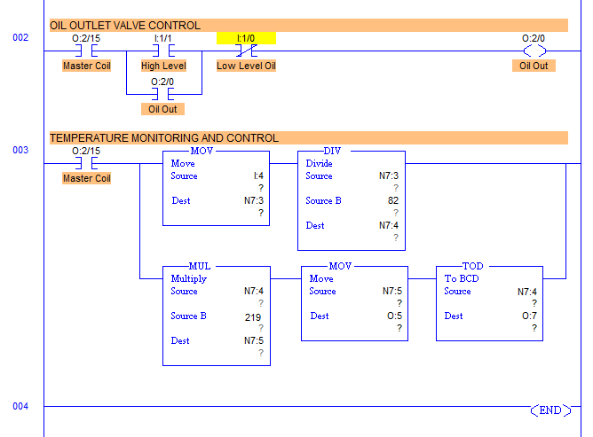
- Similarly Temperature monitoring and controlling is done as shown in the Ladder diagram below.
Ladder diagram to control and monitor Temperature of Oil and Water separation process
- Let’s say, temperature to be controlled is 50 degree centigrade. According to used sensor RTD PT100, data are processed and required temperature is controlled through Gas Supply for ignition.
- Here display output address is O:7.
- RUNG002 is to operate Oil Outlet Valve with address O:2/0.
- When Level low is detected by Low level sensor with address I:1/1, outlet valve is opened and it is closed when I:1/0 is detected that is high level.
Runtime Test Cases
Inputs     	Outputs 	Physical Elements
I:1/1 = 1	O:2/0 = 1	Open oil outlet valve
I:1/0 = 1	O:2/0 = 0	Close oil outlet valve
I:3 = 8000h	O:3 = 0000h	Close inlet valve fully
I:3 = 4000h	O:3 = 7FFFh	Inlet Valve 50% open
I:4 = 6018h	O:5 = 0000h	Gas supply valve fully closed
I:4 = 300Ch	O:5 = 8000h	Gas supply valve fully closed
Sanfoundry Global Education & Learning Series – PLC Algorithms.
To practice all PLC programs, here is complete set of 100+ PLC Problems and Solutions.

