This is a PLC Program to Control Traffic Lights and Pedestrian Lights.
Problem Description
Implement controlling of Traffic Lights and Pedestrian Lights using PLC in Ladder Diagram programming language.
Problem Solution
- As we have solved Traffic Lights problem, similarly we can solve this problem using Sequencer Output SQO instruction.
- In this program, two bits and outputs are added.
- File length, Control, File and Destination remain same.
- Mask data changes due to 2 added outputs.
- As 2 outputs are added, Mask will now have value 00FFh as total number of bits used are 8. In order to pass all 8bits, data flow is masked with 11111111 and moved to output.
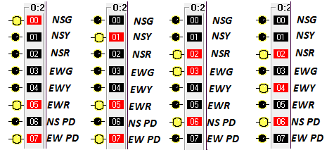
- When Green light of South-North is ON, Pedestrian Light and Red light of East-West should be ON and vice-versa.
- Use Coil to Master Start and Stop the entire process.
- While using ordinary method to Master Start and Stop, when stop is pressed, the process is just paused and is not entirely reset, hence resetting of Position in SQO instruction and Outputs using the same Stop PB can be done manually.
PLC Program
Here is PLC program to Control Traffic Lights and Pedestrian Lights, along with program explanation and run time test cases.
List of Inputs and Outputs
 I:1/0	= Start 				(Input)
 I:1/1	= Stop					(Input)
 B3:0/0	= Latched Coil Bit			(Bit)
 T4:0	= Timer to update output sequence	(Timer)
 SQO	= Sequencer output			(Sequencer)
 O:2/0	= North-South Green Light		(Output)
 O:2/1	= North-South Yellow Light		(Output)
 O:2/2	= North-South Red Light			(Output)
 O:2/3	= East-West Green Light			(Output)
 O:2/4	= East-West Yellow Light		(Output)
 O:2/5	= East-West Red Light			(Output)
 O:2/6	= South-North Pedestrian Light		(Output)
 O:2/7	= East-West Pedestrian Light		(Output)
Ladder Diagram to solve this problem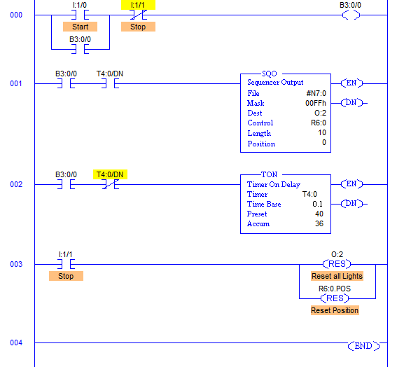
Program Description
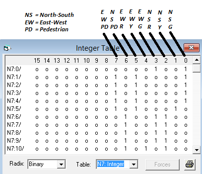
- O:2/0 to O:2/7 are used as the output address to Traffic Lights and Pedestrian Lights. Hence Mask has value 00FFh which means data flow of N7:0/0…N7:10/0 to N7:0/7…N7:10/7 is passed and the remaining N7:0/8…N7:10/8 to N7:0/15…N7:10/15 are blocked.
- Control parameters are assigned to register R6:0.
- Sequence of traffic lights and pedestrian lights to be operated are stored in the registers from N7:0 to N7:10 which is shown in the figure below.
- The entire operation is similar to that of Traffic Lights controlling.
- The only difference here is extra added outputs and different value to mask the data flow from N7:0… to O:2.
- B3:0/0 is used because it just uses a memory bit instead of wasting an output contact to use as a coil.
advertisement
advertisement
Runtime Test Cases
Sanfoundry Global Education & Learning Series – PLC Algorithms.
To practice all PLC programs, here is complete set of 100+ PLC Problems and Solutions.
