This is a PLC Program to Control Level of Two Tanks.
Problem Description
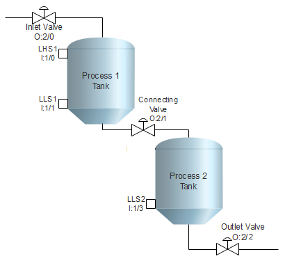
Two simultaneous processes are to be performed in two separate tanks which are connected through a valve. Process 1 takes place in the 1st tank and Process 2 takes in the 2nd tank. Control level of these tanks in PLC using Ladder Diagram programming language.
Problem Diagram
Problem Solution
- Mount two level switches in the first tank and two switches in the second tanks. Both switches of tanks detect High and Low level of the tanks.
- Install inlet valve to control inlet process flow and outlet valve to control outlet process flow.
- Install one more connecting valve to control draining of process material from Process 1 Tank to Process 2 Tank.
- Provide interlocking to prevent from malfunctioning or overflowing.
PLC Program
Here is PLC program to Control Level of Two Tanks, along with program explanation and run time test cases.
List of inputs or Outputs
 I:1/0	= Level High Switch-Tank 1, LHS1 (Input)
 I:1/1	= Level Low Switch-Tank 1, LLS1	 (Input)
 I:1/3	= Level Low Switch-Tank 2, LLS2  (Input)
 O:2/0	= Inlet Valve			 (Output)
 O:2/1	= Tank Connecting Valve		 (Output)
 O:2/2	= Outlet Valve			 (Output)
 I:1/14	= Start				 (Input)
 I:1/15	= Stop				 (Input)
 B3:0/0	= Master Coil Bit		 (Bit)
Ladder Diagram to control level of two tanks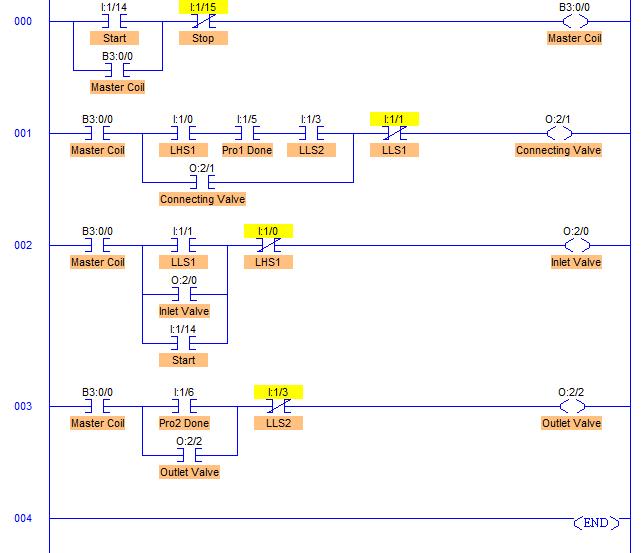
advertisement
advertisement
Program Description
- RUNG000 is a master start/stop rung to Start and Stop the entire process.
- RUNG001 is for controlling Connecting Valve output O:2/1. It is opened when LHS1 I:1/0, Pro1 Done I:1/5 and LLS2 I:1/3 are detected. And it is closed when LLS1 I:1/1 is detected, or in other words, when Process 1 Tank is empty.
- Important thing to note here is that if Tanks’ size/shape were not same and any one XIC contact from O:2/1, I:1/0 or I:1/5 was not connected, there would have been a chance of malfunctioning/overflowing.
- RUNG002 is for controlling Inlet valve O:2/0. It is allows the inlet flow by opening Inlet Valve whenever Low Level switch of Process1 Tank LLS1 with address I:1/0 is detected.
- RUNG003 is for controlling Outlet Valve with address O:2/2. It allows the process material to flow out when Pro1 Done I:1/6 is detected.
- Consider any set point of Process1 and Process2 as I:1/5 and I:1/6.
Runtime Test Cases
Inputs                           Outputs	Physical Elements
I:1/0 = 1, I:1/1 = 0	         O:2/2 = 1	Open Outlet Valve
I:1/0 = 0, I:1/1 = 1	         O:2/0 = 1	Open Inlet Valve
I:1/0 = 1, I:1/5 = 1, I:1/3 = 1	 O:2/1 = 1	Open Connecting Valve
I:1/0 = 0, I:1/1 = 0	         O:2/0 = 1	Open Inlet Valve
I:1/0 = 1       	         O:2/0 = 0	Close Inlet Valve
I:1/1 = 1       	         O:2/1 = 0	Close Connecting Valve
I:1/3 = 1	                 O:2/2 = 0	Close Outlet Valve
Sanfoundry Global Education & Learning Series – PLC Algorithms.
To practice all PLC programs, here is complete set of 100+ PLC Problems and Solutions.
