This is a PLC Program to Implement BCD to Gray Code Conversion.
Problem Description
Implementing BCD TO Gray Code conversion in PLC using Ladder Diagram programming language.
Problem Solution
- In Gray Code only one bit changes at a time.
- Writing truth table showing the relation between Binary as input and Gray code as output.
- Since input is BCD, only 10 combinations can be made using 4 bits. (0 to 9).
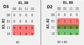
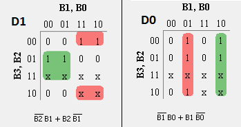
- For each Gray code output D3, D2, D1 and D0, write Karnaugh-Map.
- From the K-Map, obtaining a simplified expression for each Gray Code output in terms of BCD inputs.
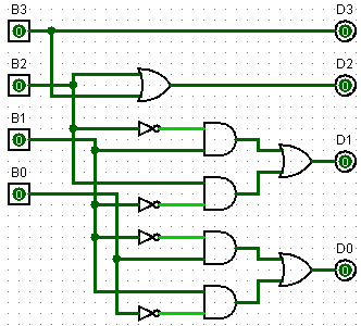
- Realize the code converter using the Logic Gates.
- By following actual process to convert BCD into Gray Code, Truth Table can be written as given below.
Truth Table relating BCD to Gray Code
Decimal	BCD input	                Gray Code output
	B3	B2	B1	B0	D3	D2	D2	D0
0	0	0	0	0	0	0	0	0
1	0	0	0	1	0	0	0	1
2	0	0	1	0	0	0	1	1
3	0	0	1	1	0	0	1	0
4	0	1	0	0	0	1	1	0
5	0	1	0	1	0	1	1	1
6	0	1	1	0	0	1	0	1
7	0	1	1	1	0	1	0	0
8	1	0	0	0	1	1	0	0
9	1	0	0	1	1	1	0	1
Boolean expression for each BCD bits can be written as
 D3= m(8, 9)
 D2= m(4, 5, 6, 7, 8, 9)
 D1= m(2, 3, 4, 5)
 D0= m(1, 2, 5, 6, 9)
advertisement
advertisement
Realizing code conversion using Logic Gates
PLC Program
Here is PLC program to Implement BCD to Gray Code Conversion, along with program explanation and run time test cases.
List of Inputs and Outputs
 B3=		I:1/0	(Input)
 B2=		I:1/1	(Input)
 B1=		I:1/2	(Input)
 B0=		I:1/3	(Input)
 D3=		O:2/0	(Output)
 D2=		O:2/1	(Output)
 D1=		O:2/2	(Output)
 D0=		O:2/3	(Output)
Ladder Diagram to obtain Gray Code output
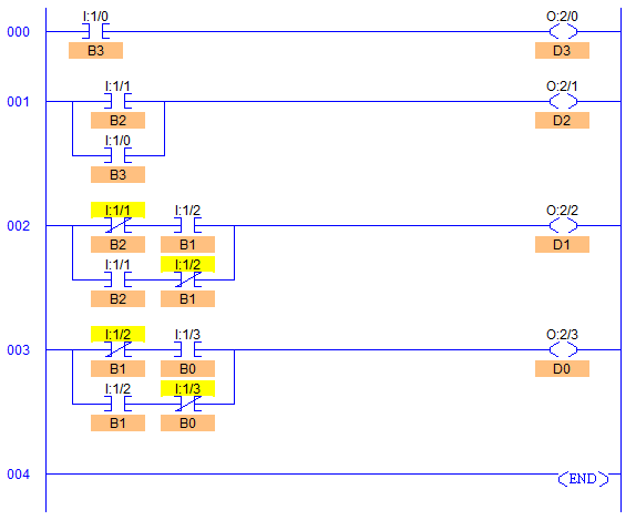
Program Description
- Simply by observing the logic circuit, ladder diagram is made.
- RUNG000 for output bit D3 (O:2/0) is as described earlier that the MSB of Gray Code and Binary are same, so passed the same B3 (I:1/0) bit directly.
- Since inputs are BCD, D2 (O:2/1) is obtained by just ORing inputs B2 (I:1/1) and B3 (I:1/0).
- By simplifying Boolean expressions, we can see that each inputs are EX-ORed with each other in different Rungs.
Runtime Test Cases
Decimal	BCD input	                Gray Code output
	B3	B2	B1	B0	D3	D2	D2	D0
0	0	0	0	0	0	0	0	0
1	0	0	0	1	0	0	0	1
2	0	0	1	0	0	0	1	1
3	0	0	1	1	0	0	1	0
4	0	1	0	0	0	1	1	0
5	0	1	0	1	0	1	1	1
6	0	1	1	0	0	1	0	1
7	0	1	1	1	0	1	0	0
8	1	0	0	0	1	1	0	0
9	1	0	0	1	1	1	0	1
Sanfoundry Global Education & Learning Series – PLC Algorithms.
To practice all PLC programs, here is complete set of 100+ PLC Problems and Solutions.
advertisement
