This is a PLC Program to Measure Time Taken by an Event.
Problem Description
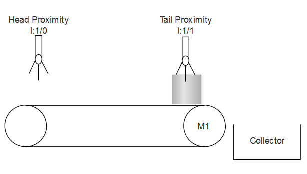
There are certain objects moving on conveyor belt. Time of an object to reach from one end to another end of the conveyor is to be measured. Implement this in PLC using Ladder Diagram programming language.
Problem Diagram
Problem Solution
- Install two proximity switches, one at the head end and another at the tail end.
- When first proximity detects an object, it latches and output starting timer.
- When another proximity placed at the tail end detects the same object, timer is stopped.
- Move preset value to any register or output displays.
- This shows time taken by an event.
- Similar phenomena can be applied to measure time taken to fill an empty tank.
PLC Program
Here is PLC program to Measure Time Taken by an Event, along with program explanation and run time test cases.
List of Inputs and Outputs
 I:1/0	= Start Measurement			(Input)
 I:1/1	= Stop Measurement			(Input)
 I:1/2	= Head proximity			(Input)
 I:1/3	= Tail Proximity			(Input)
 T4:0	= Retentive Timer to measure time	(Timer)
 N7:0	= Register to store measured time	(Register)
 O:6	= (Display) To display measured time	(Output)
-(RES)-	= Reset Retentive timer			(Reset)
Ladder Diagram to measure time taken by an event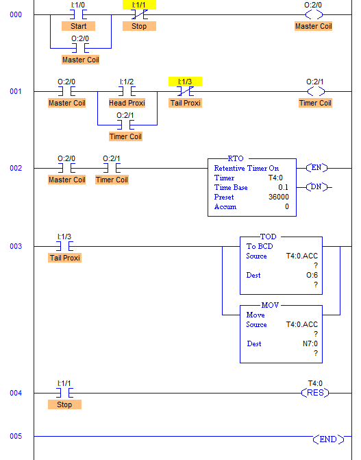
advertisement
advertisement
Program Description
- RUNG001 & RUNG002 operate Timer T4:0 through Timer Coil O:2/1. When Head Proximity Switch detects an object, it latches timer coil activating Timer T4:0.
- RUNG003 operates moving and converting of timer accumulator value. When Tail Proximity detects an object, this de-energizes Timer Coil stopping timer T4:0. And as soon as timer stops when I:1/3, it activates RUNG003 and TOD and MOV instruction are executed.
- MOV instruction moves T4:0.ACC value intro register N7:0 and TOD instruction converts Decimal data into equivalent BCD code to operate Display with address O:6. Digits displayed on the display is time taken by an event.
- Retentive timer is used here so that when Tail Proximity detects the object and Master Coil is de-energized, value in the accumulator do not change.
Runtime Test Cases
Inputs	        Outputs 	Physical Elements
I:1/2 = 1	O:2/1 = 1	Enable Timer
I:1/3 = 1	O:2/1 = 0	Disable Timer, Convert into BCD, Move data
I:1/1 = 1       -(RES)- = 1	Stop Measurement, Reset Timer
Sanfoundry Global Education & Learning Series – PLC Algorithms.
To practice all PLC programs, here is complete set of 100+ PLC Problems and Solutions.
