This set of Logic Design Multiple Choice Questions & Answers (MCQs) focuses on “Registers and Register Transfers”.
1. A D Flip-Flop can store 2 bits of information. True or False?
a) True
b) False
View Answer
Explanation: A D Flip-Flop can store only 1 bit of information, since the inputs and outputs are 1 bit wide. At an instance it can store either 0 or 1. A D Flip-Flop cannot store more than 1 bit of information.
2. If ‘n’ number of D Flip-Flops are grouped together with a common clock to form a register, then that register can store ‘n’ bits of information.
a) True
b) False
View Answer
Explanation: A D Flip-Flop can store only 1 bit of information, since the inputs and outputs are 1 bit wide. So, if a register has ‘n’ D Flip-Flops with a common clock, then it can store ‘n’ bits of information.
3. In Digital Electronics, what is a bus?
a) A wire
b) A pin of an integrated circuit
c) A kind of Random Access Memory
d) A group of wires that perform a common function
View Answer
Explanation: A group of wires that perform a common function is referred to as a bus. Example for a bus is the USB (Universal Serial Bus). Busses are used when many bits of data need to be transferred between devices.
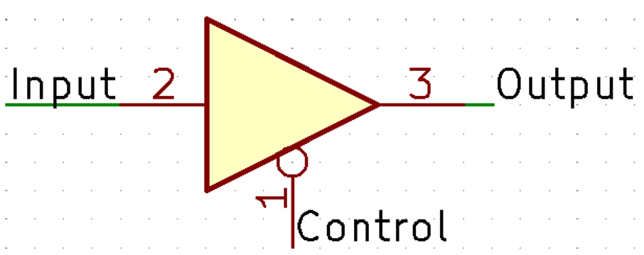
4. Identify the electronic device associated with the following symbol.

a) Tri-state buffer with active low control
b) Tri-state buffer with active high control
c) 3:1 Multiplexer
d) NOT gate
View Answer
Explanation: The above symbol is that of a tri-state buffer with Active Low control. The bubble on the control input indicates that it is Active low.
Truth table:
| Control | Output |
|---|---|
| 0 | Input |
| 1 | Z (High Impedance) |
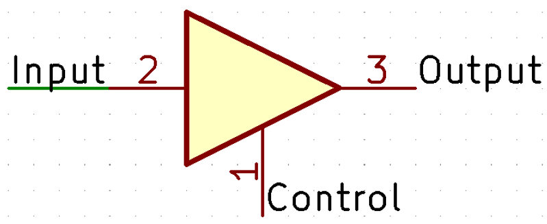
5. Identify the electronic device associated with the following symbol.

a) Tri-state buffer with active low control
b) Tri-state buffer with active high control
c) 3:1 Multiplexer
d) NOT gate
View Answer
Explanation: The above symbol is that of a tri-state buffer with Active High control.
Truth table:
| Control | Output |
|---|---|
| 0 | Z (High Impedance) |
| 1 | Input |
6. Identify the electronic device associated with the following symbol.

a) Buffer
b) NOT gate
c) OR gate
d) NOR gate
View Answer
Explanation: The above symbol is that of a buffer. The output of a buffer is 0 when the input is 0 and 1 when the input is 1. A buffer can also be obtained by cascading 2 NOT gates.
Sanfoundry Global Education & Learning Series – Logic Design.
To practice all areas of Logic Design, here is complete set of 1000+ Multiple Choice Questions and Answers.
If you find a mistake in question / option / answer, kindly take a screenshot and email to [email protected]
