This set of Sequential Logic Design Multiple Choice Questions & Answers (MCQs) focuses on “Modeling Flip-Flops Using VHDL Processes”.
1. Write the VHDL architecture “behaviour” for the given entity of the positive edge triggered D flip-flop using behavioral modeling. The clock is clk, the input is D, the outputs are Q and Q_n. Q_n is the complement of Q. Assume that the IEEE library and std_logic_1164 package are included.
entity DFF is
port (clk, D: in std_logic;
    Q, Q_n:out std_logic);
end entity DFF;
a)
architecture behaviour of DFF is
signal QINT: std_logic;
begin
Q <= QINT;
Q_n <= not QINT;
process (clk) is
begin
if rising_edge(clk) then
   QINT <= D;
end if;
end process;
end behaviour;
b)
architecture behaviour of DFF is
begin
process (clk) is
begin
if rising_edge(clk) then
    QINT <= D;
end if;
end process;
end behaviour;
c)
architecture behaviour of DFF is
signal QINT: std_logic;
begin
Q <= QINT;
Q_n <= not QINT;
process (clk) is
begin
if rising_edge(clk) then
   QINT <= D;
end if;
end behaviour;
d)
architecture behaviour of DFF is
signal QINT: std_logic;
begin
Q <= QINT;
Q_n <= not QINT;
process (clk) is
begin
if rising_edge(clk) then
   QINT <= D;
end if;
end process;
Explanation:
architecture behaviour of DFF is   -- declare architecture behaviour
signal QINT: std_logic;     -- intermediate signal QINT
begin     -- start of architecture code
Q <= QINT;    -- output Q is assigned the value from QINT
Q_n <= not QINT;   -- output Q_n is assigned the complement of the value from Q_n
process (clk) is   -- declare a process sensitive to the clock clk
begin  -- start process
if rising_edge(clk) then      -- positive edge triggered clock, so trigger on the rising edge
   QINT <= D;      -- if rising edge of the clock is detected, the signal QINT is assigned the value of D
end if;         -- end of if condition
end process;       -- end process
end behaviour;       -- end architecture behaviour
2. Write the VHDL behavioural code of a positive edge triggered D Flip-Flop which has a synchronous reset input. The reset is active HIGH. The clock is clk, the inputs are D and reset, and there is a single output Q. Assume that the IEEE library and std_logic_1164 package are included.
a)
entity DFF is
port (clk, D, reset: in std_logic;
    Q:out std_logic);
end entity DFF;
architecture behaviour of DFF is
begin
process (clk) is
begin
if rising_edge(clk) then
    if reset = '1' then
        Q <= '0';
    else
        Q <= D;
    end if;
end if;
end process;
end behaviour;
b)
entity DFF is
port (clk, D, reset: in std_logic;
    Q:out std_logic);
end entity DFF;
architecture behaviour of DFF is
begin
process (clk, reset) is
begin
if rising_edge(clk) then
    if reset = '1' then
        Q <= '0';
    else
        Q <= D;
    end if;
end if;
end process;
end behaviour;
c)
entity DFF is
port (clk, D, reset: in std_logic;
    Q:out std_logic);
end entity DFF;
architecture behaviour of DFF is
begin
process (clk, reset) is
begin
if rising_edge(clk) then
    if reset = '1' then
        Q <= '0';
    else
        Q <= D;
    end if;
end process;
end behaviour;
d)
entity DFF is
port (clk, D, reset: in std_logic;
    Q:out std_logic);
end entity DFF;
architecture behaviour of DFF is
begin
process (clk) is
begin
if rising_edge(clk) then
    if reset = '1' then
        Q <= '0';
    end if;
end if;
end process;
end behaviour;
Explanation: The VHDL behavioural code for a positive edge triggered D Flip-Flop, with a single output Q which has an Active HIGH synchronous reset input is given by:
entity DFF is
port (clk, D, reset: in std_logic;
    Q:out std_logic);
end entity DFF;
architecture behaviour of DFF is  -- declare architecture behaviour
begin   -- start of architecture code
process (clk) is  -- declare a process sensitive to the clock clk since the reset is synchronous
begin  -- start process
if rising_edge(clk) then  --  positive edge triggered clock, so trigger on the rising edge
    if reset = '1' then   -- if reset is asserted,  Q is reset to 0
        Q <= '0';
    else  -- if reset is not asserted, Q is assigned the value of D
        Q <= D;
    end if;
end if;
end process;
end behaviour;
3. Write the VHDL behavioural code of a positive edge triggered D Flip-Flop which has an asynchronous reset input. The reset is active HIGH. The clock is clk, the inputs are D and reset, and there is a single output Q. Assume that the IEEE library and std_logic_1164 package are included.
a)
entity DFF is
port (clk, D, reset: in std_logic;
    Q:out std_logic);
end entity DFF;
architecture behaviour of DFF is
begin
process (clk) is
begin
if rising_edge(clk) then
    if reset = '1' then
        Q <= '0';
    else
        Q <= D;
    end if;
end if;
end process;
end behaviour;
b)
entity DFF is
port (clk, D, reset: in std_logic;
    Q:out std_logic);
end entity DFF;
architecture behaviour of DFF is
begin
process (clk, reset) is
begin
if reset = '1' then
   Q <= '0';
else if rising_edge(clk)  then
   Q <= D;
end if;
end if;
end process;
end behaviour;
c)
entity DFF is
port (clk, D, reset: in std_logic;
    Q:out std_logic);
end entity DFF;
architecture behaviour of DFF is
begin
process (clk, reset) is
begin
if rising_edge(clk) then
    if reset = '1' then
        Q <= '0';
    else
        Q <= D;
    end if;
end process;
end behaviour;
d)
entity DFF is
port (clk, D, reset: in std_logic;
    Q:out std_logic);
end entity DFF;
architecture behaviour of DFF is
begin
process (clk) is
begin
if rising_edge(clk) then
    if reset = '1' then
        Q <= '0';
    end if;
end if;
end process;
end behaviour;
Explanation: The VHDL behavioural code for a positive edge triggered D Flip-Flop, with a single output Q which has an Active HIGH asynchronous reset input is given by:
entity DFF is
port (clk, D, reset: in std_logic;
    Q:out std_logic);
end entity DFF;
architecture behaviour of DFF is  -- declare architecture behaviour
begin   -- start of architecture code
process (clk, reset) is  -- declare a process sensitive to the clock clk and reset
begin  -- start process
if reset = '1' then  -- if reset is asserted,  then Q is reset to 0
    Q <= '0';
else if rising_edge(clk)  then -- if reset is not asserted and the rising edge of the clock is detected then
    Q <= D;  -- Q Is assigned the value of D
end if;
end if;
end process;
end behaviour;
4. Write the VHDL behavioural code of a positive edge triggered D Flip-Flop which has a synchronous reset input. The reset is active LOW. The clock is clk, the inputs are D and reset, and there is a single output Q. Assume that the IEEE library and std_logic_1164 package are included.
a)
entity DFF is
port (clk, D, reset: in std_logic;
    Q:out std_logic);
end entity DFF;
architecture behaviour of DFF is
begin
process (clk) is
begin
if rising_edge(clk) then
   if reset = '0' then
       Q <= '0';
   else
       Q <= D;
   end if;
end if;
end process;
end behaviour;
b)
entity DFF is
port (clk, D, reset: in std_logic;
    Q:out std_logic);
end entity DFF;
architecture behaviour of DFF is
begin
process (clk, reset) is
begin
if rising_edge(clk) then
    if reset = '0' then
        Q <= '0';
    else
        Q <= D;
    end if;
end if;
end process;
end behaviour;
c)
entity DFF is
port (clk, D, reset: in std_logic;
    Q:out std_logic);
end entity DFF;
architecture behaviour of DFF is
begin
process (clk, reset) is
begin
if rising_edge(clk) then
    if reset = '1' then
        Q <= '0';
    else
        Q <= D;
    end if;
end process;
end behaviour;
d)
entity DFF is
port (clk, D, reset: in std_logic;
    Q:out std_logic);
end entity DFF;
architecture behaviour of DFF is
begin
process (clk) is
begin
if rising_edge(clk) then
    if reset = '0' then
        Q <= '0';
    end if;
end if;
end process;
end behaviour;
Explanation: The VHDL behavioural code for a positive edge triggered D Flip-Flop, with a single output Q which has an Active LOW synchronous reset input is given by:
entity DFF is
port (clk, D, reset: in std_logic;
    Q:out std_logic);
end entity DFF;
architecture behaviour of DFF is  -- declare architecture behaviour
begin   -- start of architecture code
process (clk) is  -- declare a process sensitive to the clock clk since the reset is synchronous
begin  -- start process
if rising_edge(clk) then  --  positive edge triggered clock, so trigger on the rising edge
    if reset = '0' then   -- if reset is asserted,  Q is reset to 0
        Q <= '0';
    else  -- if reset is not asserted, Q is assigned the value of D
        Q <= D;
    end if;
end if;
end process;
end behaviour;
5. Write the VHDL behavioural code of a positive edge triggered D Flip-Flop which has an asynchronous reset input. The reset is active LOW. The clock is clk, the inputs are D and reset, and there is a single output Q. Assume that the IEEE library and std_logic_1164 package are included.
a)
entity DFF is
port (clk, D, reset: in std_logic;
    Q:out std_logic);
end entity DFF;
architecture behaviour of DFF is
begin
process (clk) is
begin
if rising_edge(clk) then
    if reset = '0' then
        Q <= '0';
    else
        Q <= D;
    end if;
end if;
end process;
end behaviour;
b)
entity DFF is
port (clk, D, reset: in std_logic;
    Q:out std_logic);
end entity DFF;
architecture behaviour of DFF is
begin
process (clk, reset) is
begin
if reset = '0' then
    Q <= '0';
else if rising_edge(clk)  then
    Q <= D;
end if;
end if;
end process;
end behaviour;
c)
entity DFF is
port (clk, D, reset: in std_logic;
    Q:out std_logic);
end entity DFF;
architecture behaviour of DFF is
begin
process (clk, reset) is
begin
if rising_edge(clk) then
    if reset = '0' then
        Q <= '0';
    else
        Q <= D;
    end if;
end process;
end behaviour;
d)
entity DFF is
port (clk, D, reset: in std_logic;
    Q:out std_logic);
end entity DFF;
architecture behaviour of DFF is
begin
process (clk) is
begin
if rising_edge(clk) then
    if reset = '0' then
        Q <= '0';
    end if;
end if;
end process;
end behaviour;
Explanation: The VHDL behavioural code for a positive edge triggered D Flip-Flop, with a single output Q which has an Active LOW asynchronous reset input is given by:
entity DFF is
port (clk, D, reset: in std_logic;
    Q:out std_logic);
end entity DFF;
architecture behaviour of DFF is  -- declare architecture behaviour
begin   -- start of architecture code
process (clk, reset) is  -- declare a process sensitive to the clock clk and reset
begin  -- start process
if reset = '0' then   -- if reset is asserted,  Q is reset to 0
   Q <= '0';
else if rising_edge(clk) then -- if reset is not asserted and the rising edge of the clock is detected then
  Q <= D;   --Q is assigned the value of D
end if;
end if;
end process;
end behaviour;
6. Write the VHDL behavioural code for a J-K Flip-Flop with a rising edge triggered clock. The inputs are J, K and clk. The outputs are Q and Q_bar. Q_bar is the complement of Q. Assume that the IEEE library and std_logic_1164 package are included.
a)
entity JK_FF is
port (J, K, CLK: in std_logic; -- inputs
    Q, Q_bar: out std_logic);
end entity JK_FF;

architecture behaviour of JK_FF is
signal QINT:std_logic;
begin
process (CLK)
    variable JK : std_logic_vector( 1 downto 0);
    begin
    JK := J & K;
    if rising_edge(clk) then
        case (JK) is
        when "00" => QINT <= QINT;
        when "01" => QINT <= '0';
        when "10" => QINT <= '1';
        when "11" => QINT <= not QINT;
        when others => QINT <= 'X';
        end case;
    end if;
end process;
Q <= QINT;
Q_bar <= not QINT;
end behaviour;
b)
entity JK_FF is
port (J, K, CLK: in std_logic; -- inputs
    Q, Q_bar: out std_logic);
end entity JK_FF;

architecture behaviour of JK_FF is
signal QINT:std_logic;
begin
process (CLK)
    variable JK : std_logic_vector( 1 downto 0);
    begin
    JK := J & K;
    if rising_edge(clk) then
        case (JK) is
        when "00" => QINT <= QINT;
        when "01" => QINT <= '1';
        when "10" => QINT <= '0';
        when "11" => QINT <= not QINT;
        when others => QINT <= 'X';
        end case;
    end if;
end process;
Q <= QINT;
Q_bar <= not QINT;
end behaviour;
c)
entity JK_FF is
port (J, K, CLK: in std_logic; -- inputs
    Q, Q_bar: out std_logic);
end entity JK_FF;

architecture behaviour of JK_FF is
signal QINT:std_logic;
begin
process (CLK)
    variable JK : std_logic_vector( 1 downto 0);
    begin
    JK := J & K;
    if rising_edge(clk) then
        case (JK) is
        when "00" => QINT <= not QINT;
        when "01" => QINT <= '0';
        when "10" => QINT <= '1';
        when "11" => QINT <= QINT;
        when others => QINT <= 'X';
        end case;
    end if;
end process;
Q <= QINT;
Q_bar <= not QINT;
end behaviour;
d)
entity JK_FF is
port (J, K, CLK: in std_logic; -- inputs
    Q, Q_bar: out std_logic);
end entity JK_FF;

architecture behaviour of JK_FF is
signal QINT:std_logic;
begin
process (CLK)
    variable JK : std_logic_vector( 1 downto 0);
    begin
    JK := J & K;
    if rising_edge(clk) then
        case (JK) is
        when "00" => Q <= QINT;
        when "01" => Q <= '0';
        when "10" => Q <= '1';
        when "11" => Q <= not QINT;
        when others => Q <= 'X';
        end case;
    end if;
end process;
end behaviour;
Explanation:
The state-transition table of a JK Flip Flop is:
| J | K | Q+ |
|---|---|---|
| 0 | 0 | Q |
| 0 | 1 | 0 |
| 1 | 0 | 1 |
| 1 | 1 | ¬Q |
Based on this table the VHDL code is written.
7. Write the VHDL architecture ‘struct’ of a T Flip Flop using a JK Flip-Flop. Assume that the IEEE library and std_logic_1164 package are included. The resets of the JK Flip-Flop and T Flip-Flop are active HIGH and synchronous.
The entity of the T Flip-Flop is:
entity T_FF is
port (T, clk, reset : in std_logic;
    Q, Q_bar: out std_logic);
end entity T_FF;
The entity of the J-K Flip-Flop is:
entity JK_FF is
port (J, K, CLK, reset: in std_logic; -- inputs
    Q, Q_bar: out std_logic);
end entity JK_FF;
a)
architecture struct of T_FF is
component JK_FF
port (J, K, CLK, reset: in std_logic; -- inputs
    Q, Q_bar: out std_logic);
end component JK_FF;
begin
jk_ff0 : jk_ff port map(J => T, K => T, CLK => CLK, reset => reset, Q => Q, Q_bar=>Q_bar);
end architecture struct;
b)
architecture struct of T_FF is
component JK_FF
port (J, K, CLK, reset: in std_logic; -- inputs
    Q, Q_bar: out std_logic);
end component JK_FF;
begin
jk_ff0 : jk_ff port map(J, K => T, CLK => CLK, reset => reset, Q => Q, Q_bar => Q_bar);
end architecture struct;
c)
architecture struct of T_FF is
component JK_FF
port (J, K, CLK, reset: in std_logic; -- inputs
    Q, Q_bar: out std_logic);
end component JK_FF;
begin
jk_ff0 : jk_ff port map(J & K => T, CLK => CLK, reset => reset, Q => Q, Q_bar => Q_bar);
end architecture struct;
d)
architecture struct of T_FF is
component JK_FF
port (J, K, CLK, reset: in std_logic; -- inputs
    Q, Q_bar: out std_logic);
end component JK_FF;
begin
jk_ff0 : jk_ff port map(J => T, CLK => CLK, reset => reset, Q => Q, Q_bar => Q_bar);
end architecture struct;
Explanation: A T Flip-Flop is built from a J-K Flip-Flop by connecting the J and K inputs together to form the T input. The state-transition table of a T Flip-Flop with an Active HIGH synchronous reset is:
| T | Reset | Q+ |
|---|---|---|
| X | 1 | 0 |
| 0 | 0 | Q |
| 1 | 0 | ¬Q |
8. Write the VHDL behavioural code for a J-K Flip-Flop with a rising edge triggered clock and a synchronous active HIGH reset. The inputs are J, K, clk and reset. The outputs are Q and Q_bar. Q_bar is the complement of Q. Assume that the IEEE library and std_logic_1164 package are included.
a)
entity JK_FF is
port (J, K, CLK, reset: in std_logic; -- inputs
    Q, Q_bar: out std_logic);
end entity JK_FF;

architecture behaviour of JK_FF is
signal QINT:std_logic;
begin
process (CLK)
    variable JK : std_logic_vector( 1 downto 0);
    begin
    JK := J & K;
    if rising_edge(clk) then
        if reset = '1' then
            QINT <= '0';
        else
            case (JK) is
            when "00" => QINT <= QINT;
            when "01" => QINT <= '0';
            when "10" => QINT <= '1';
            when "11" => QINT <= not QINT;
            when others => QINT <= 'X';
            end case;
        end if;
    end if;
end process;
Q <= QINT;
Q_bar <= not QINT;
end behaviour;
b)
entity JK_FF is
port (J, K, CLK, reset: in std_logic; -- inputs
    Q, Q_bar: out std_logic);
end entity JK_FF;

architecture behaviour of JK_FF is
signal QINT:std_logic;
begin
process (CLK)
    variable JK : std_logic_vector( 1 downto 0);
    begin
    JK := J & K;
    if rising_edge(clk) then
        if reset = '1' then
            QINT <= '0';
        else
            case (JK) is
            when "00" => QINT <= QINT;
            when "01" => QINT <= '1';
            when "10" => QINT <= '0';
            when "11" => QINT <= not QINT;
            when others => QINT <= 'X';
            end case;
       end if;
    end if;
end process;
Q <= QINT;
Q_bar <= not QINT;
end behaviour;
c)
entity JK_FF is
port (J, K, CLK, reset: in std_logic; -- inputs
    Q, Q_bar: out std_logic);
end entity JK_FF;

architecture behaviour of JK_FF is
signal QINT:std_logic;
begin
process (CLK)
    variable JK : std_logic_vector( 1 downto 0);
    begin
    JK := J & K;
    if rising_edge(clk) then
        if reset = '1' then
            QINT <= '0';
        else
            case (JK) is
            when "00" => QINT <= not QINT;
            when "01" => QINT <= '1';
            when "10" => QINT <= '0';
            when "11" => QINT <= QINT;
            when others => QINT <= 'X';
            end case;
        end if;
    end if;
end process;
Q <= QINT;
Q_bar <= not QINT;
end behaviour;
d)
entity JK_FF is
port (J, K, CLK, reset: in std_logic; -- inputs
    Q, Q_bar: out std_logic);
end entity JK_FF;

architecture behaviour of JK_FF is
signal QINT:std_logic;
begin
process (CLK)
    variable JK : std_logic_vector( 1 downto 0);
    begin
    JK := J & K;
    if rising_edge(clk) then
        if reset = '1' then
            QINT <= '0';
        else
            case (JK) is
            when "00" => QINT <= QINT;
            when "01" => QINT <= '0';
            when "10" => QINT <= '1';
            when "11" => QINT <= not QINT;
            when others => QINT <= 'X';
            end case;
        end if;
    end if;
end process;
end behaviour;
Explanation:
The state-transition table of a J-K Flip Flop with an active HIGH synchronous reset is given by:
| J | K | Reset | Q+ |
|---|---|---|---|
| X | X | 1 | 0 |
| 0 | 0 | 0 | Q |
| 0 | 1 | 0 | 0 |
| 1 | 0 | 0 | 1 |
| 1 | 1 | 0 | ¬Q |
Based on this table the VHDL code is written.
9. Write the VHDL behavioural code for a J-K Flip-Flop with a rising edge triggered clock and a synchronous active LOW reset. The inputs are J, K, clk and reset_n. The outputs are Q and Q_bar. Q_bar is the complement of Q. Assume that the IEEE library and std_logic_1164 package are included.
a)
entity JK_FF is
port (J, K, CLK, reset_n: in std_logic; -- inputs
    Q, Q_bar: out std_logic);
end entity JK_FF;

architecture behaviour of JK_FF is
signal QINT:std_logic;
begin
process (CLK)
    variable JK : std_logic_vector( 1 downto 0);
    begin
    JK := J & K;
    if rising_edge(clk) then
        if reset_n = '0' then
            QINT <= '0';
        else
            case (JK) is
            when "00" => QINT <= QINT;
            when "01" => QINT <= '0';
            when "10" => QINT <= '1';
            when "11" => QINT <= not QINT;
            when others => QINT <= 'X';
            end case;
        end if;
    end if;
end process;
Q <= QINT;
Q_bar <= not QINT;
end behaviour;
b)
entity JK_FF is
port (J, K, CLK, reset_n: in std_logic; -- inputs
    Q, Q_bar: out std_logic);
end entity JK_FF;

architecture behaviour of JK_FF is
signal QINT:std_logic;
begin
process (CLK)
    variable JK : std_logic_vector( 1 downto 0);
    begin
    JK := J & K;
    if rising_edge(clk) then
        if reset_n = '1' then
            QINT <= '0';
        else
            case (JK) is
            when "00" => QINT <= QINT;
            when "01" => QINT <= '1';
            when "10" => QINT <= '0';
            when "11" => QINT <= not QINT;
            when others => QINT <= 'X';
            end case;
        end if;
    end if;
end process;
Q <= QINT;
Q_bar <= not QINT;
end behaviour;
c)
entity JK_FF is
port (J, K, CLK, reset_n: in std_logic; -- inputs
    Q, Q_bar: out std_logic);
end entity JK_FF;

architecture behaviour of JK_FF is
signal QINT:std_logic;
begin
process (CLK)
    variable JK : std_logic_vector( 1 downto 0);
    begin
    JK := J & K;
    if rising_edge(clk) then
        if reset_n = '0' then
            QINT <= '0';
        else
            case (JK) is
            when "00" => QINT <= not QINT;
            when "01" => QINT <= '1';
            when "10" => QINT <= '0';
            when "11" => QINT <= QINT;
            when others => QINT <= 'X';
            end case;
        end if;
    end if;
end process;
Q <= QINT;
Q_bar <= not QINT;
end behaviour;
d)
entity JK_FF is
port (J, K, CLK, reset_n: in std_logic; -- inputs
    Q, Q_bar: out std_logic);
end entity JK_FF;

architecture behaviour of JK_FF is
signal QINT:std_logic;
begin
process (CLK)
    variable JK : std_logic_vector( 1 downto 0);
    begin
    JK := J & K;
    if rising_edge(clk) then
        if reset_n = '0' then
            QINT <= '0';
        else
            case (JK) is
            when "00" => QINT <= QINT;
            when "01" => QINT <= '0';
            when "10" => QINT <= '1';
            when "11" => QINT <= not QINT;
            when others => QINT <= 'X';
            end case;
        end if;
    end if;
end process;
end behaviour;
Explanation:
The state-transition table of a J-K Flip Flop with an active HIGH synchronous reset is given by:
| J | K | Reset n | Q+ |
|---|---|---|---|
| x | x | 0 | 0 |
| 0 | 0 | 1 | Q |
| 0 | 1 | 1 | 0 |
| 1 | 0 | 1 | 1 |
| 1 | 1 | 1 | ¬Q |
Based on this table the VHDL code is written.
10. Write the VHDL architecture ‘struct_and_dataflow’ for a T Flip-Flop using a D Flip-Flop. The resets of both the T and D flip-flops are synchronous and active HIGH. Assume that the IEEE library and std_logic_1164 package are included. Q-bar is the complement of Q.
The entity of the T Flip-Flop is
entity T_FF is
port (T, clk, reset : in std_logic;
    Q, Q_bar: out std_logic);
end entity T_FF;
The entity of the D Flip-Flop is
entity DFF is
port (D, CLK, reset: in std_logic; -- inputs
    Q: out std_logic);
end entity DFF;
a)
architecture struct_and_dataflow of T_FF is
signal d_int: std_logic;
component DFF
port (D, CLK, reset: in std_logic; -- inputs
    Q: out std_logic);
end component DFF;
begin
d_ff0: dff port map(D => d_int, clk => clk, reset => reset, Q => Q);
d_int <= T xor Q;
Q_bar <= not Q;
end architecture struct_and_dataflow;
b)
architecture struct_and_dataflow of T_FF is
signal d_int: std_logic;
component DFF
port (D, CLK, reset: in std_logic; -- inputs
    Q: out std_logic);
end component DFF;
begin
d_ff0: dff port map(D => d_int, clk => clk, reset => reset, Q => Q);
d_int <= T or Q;
Q_bar <= not Q;
end architecture struct_and_dataflow;
c)
architecture struct_and_dataflow of T_FF is
signal d_int: std_logic;
component DFF
port (D, CLK, reset: in std_logic; -- inputs
    Q: out std_logic);
end component DFF;
begin
d_ff0: dff port map(D => d_int, clk => clk, reset => reset, Q => Q);
d_int <= T xor Q;
end architecture struct_and_dataflow;
d)
architecture struct_and_dataflow of T_FF is
signal d_int: std_logic;
component DFF
port (D, CLK, reset: in std_logic; -- inputs
    Q: out std_logic);
end component DFF;
begin
d_ff0: dff port map(D => d_int, clk => clk, reset => reset, Q => Q);
d_int <= T and Q;
Q_bar <= not Q;
end architecture struct_and_dataflow;
Explanation:
The logic diagram for the given question is:
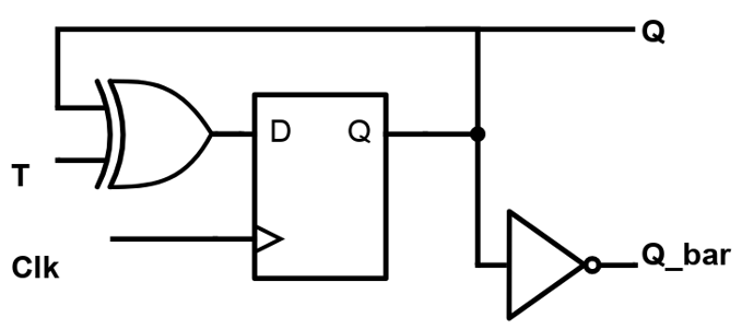
The D input is Q ⊕ T. So Q + = Q ⊕ T = T.Q’ + T’.Q, which is the characteristic equation of the T flip-flop. Since the characteristic equation uses an Exclusive OR operation, an XOR gate is used, as shown in the above figure. Based on this logic diagram the VHDL code is written.
11. Write the VHDL architecture “behaviour” for the given entity of the transparent D latch using behavioral modeling. The enable is en, the input is D, the output is Q. Assume that the IEEE library and std_logic_1164 package are included.
entity D_latch is
port (en, D: in std_logic;
    Q:out std_logic);
end entity D_latch;
a)
architecture behaviour of D_latch is
begin
process (en) is
begin
if rising_edge(en) then
    Q <= D;
end if;
end process;
end behaviour;
b)
architecture behaviour of D_latch is
begin
process (en) is
begin
if (en) then
    Q <= D;
end if;
end process;
end behaviour;
c)
architecture behaviour of D_latch is
begin
process (en, D) is
begin
if en = ‘1’ then
    Q <= D;
end if;
end behaviour;
d)
architecture behaviour of D_latch is
begin
process (D) is
begin
if (en) then
    Q <= D;
end if;
end process;
Explanation:
architecture behaviour of D_latch is   -- declare architecture behaviour
begin     -- start of architecture code
process (en, D) is   -- declare a process sensitive to the enable input and data input
begin  -- start process
if en = ‘1’ then      -- a transparent latch, so trigger on the level
   Q <= D;      -- signal Q is assigned the value of D if en is equal to 1
end if;         -- end of if condition
end process;       -- end process
end behaviour;      -- end architecture behaviour
12. Write the VHDL architecture “behaviour” for the given entity of an SR Latch using behavioural modelling. The inputs are S and R. Both inputs are Active HIGH. The outputs are Q and Q_bar. Q_bar is the complement of Q. Assume that the IEEE library and std_logic_1164 package are included.
entity SR_latch is
port (S, R: in std_logic;
    Q, Q_bar:out std_logic);
end entity SR_latch;
a)
architecture behaviour of SR_latch is
begin
process (S, R) is
variable SR: std_logic_vector(1 downto 0);
begin  -- start process
    SR := S & R;
    case (SR) is
    when "00" => Q <= Q;
    when "10" => Q <= '1';
    when "01" => Q <= '0';
    when "11" => Q <= 'X';
    when others => Q <= 'Z';
    end case;
end process;
Q_bar <= not Q;
end;
b)
architecture behaviour of SR_latch is
begin
process (S, R) is
variable SR: std_logic_vector(1 downto 0);
begin  -- start process
    SR := S & R;
    case (SR) is
    when "00" => Q <= Q;
    when "10" => Q <= '1';
    when "01" => Q <= '1';
    when "11" => Q <= 'X';
    when others => Q <= 'Z';
    end case;
end process;
end;
c)
architecture behaviour of SR_latch is
begin
process (S, R) is
variable SR: std_logic_vector(1 downto 0);
begin  -- start process
    SR := S & R;
    case (SR) is
    when "00" => Q <= Q;
    when "10" => Q <= '0';
    when "01" => Q <= '1';
    when "11" => Q <= 'X';
    when others => Q <= 'Z';
    end case;
end process;
Q_bar <= not Q;
end;
d)
architecture behaviour of SR_latch is
begin
process (S, R) is
begin  -- start process
    case (S) is
    when "00" => Q <= Q;
    when "10" => Q <= '1';
    when "01" => Q <= '0';
    when "11" => Q <= 'X';
    when others => Q <= 'Z';
    end case;
end process;
Q_bar <= not Q;
end;
Explanation:
The truth table of the SR Latch, with 2 outputs Q and Q_bar is given below:
| S | R | Q | Q_bar |
|---|---|---|---|
| 0 | 0 | Latch | Latch |
| 0 | 1 | 0 | 1 |
| 1 | 0 | 1 | 0 |
| 1 | 1 | Metastable | Metastable |
Based on the truth table the VHDL code is written for behavioural modeling.
13. Write the VHDL architecture “struct” for the given entity of an SR Latch using structural modelling. The inputs are S and R. Both inputs are Active HIGH. The outputs are Q and Q_bar. Q_bar is the complement of Q. Use NOR gates. Assume that the IEEE library and std_logic_1164 package are included.
entity SR_latch is
port (S, R: in std_logic;
    Q, Q_bar:out std_logic);
end entity SR_latch;
a)
architecture struct of SR_latch is
begin
Q <= Q_bar nor R;
Q_bar <= Q nor S;
end;
b)
architecture struct of SR_latch is
begin
process (S, R) is
variable SR: std_logic_vector(1 downto 0);
begin  -- start process
    SR := S & R;
    case (SR) is
    when "00" => Q <= Q;
    when "10" => Q <= '1';
    when "01" => Q <= '0';
    when "11" => Q <= 'X';
    when others => Q <= 'Z';
    end case;
end process;
Q_bar <= not Q;
end;
c)
architecture struct of SR_latch is
begin
Q <= Q_bar or R;
Q_bar <= Q or S;
end;
d)
architecture struct of SR_latch is
begin
Q <= Q_bar and R;
Q_bar <= Q and S;
end;
Explanation:
The logic diagram of an SR Latch is given below.
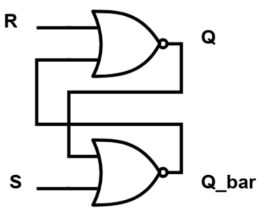
This SR Latch is designed using 2 cross-coupled NOR gates. S stands for SET input and R stands for RESET Input. Based on the above logic diagram the structural VHDL code of the SR Latch is written.
14. Write the VHDL architecture “behaviour” for the given entity of an SR Latch with an enable input using behavioural modelling. The inputs are S, R and enable. All inputs are Active HIGH. The outputs are Q and Q_bar. Q_bar is the complement of Q. Assume that the IEEE library and std_logic_1164 package are included.
entity SR_latch is
port (S, R, enable: in std_logic;
    Q, Q_bar:out std_logic);
end entity SR_latch;
a)
architecture behaviour of SR_latch is
begin
process (S, R, enable) is
variable SR: std_logic_vector(1 downto 0);
begin
    SR := S & R;
    if enable = '0' then
        Q <= Q;
    else
        case (SR) is
        when "00" => Q <= Q;
        when "10" => Q <= '1';
        when "01" => Q <= '0';
        when "11" => Q <= 'X';
        when others => Q <= 'Z';
        end case;
    end if;
end process;
Q_bar <= not Q;
end;
b)
architecture behaviour of SR_latch is
begin
process (S, R, enable) is
variable SR: std_logic_vector(1 downto 0);
begin
    SR := S & R;
    if enable = '1' then
        Q <= Q;
    else
        case (SR) is
        when "00" => Q <= Q;
        when "10" => Q <= '1';
        when "01" => Q <= '0';
        when "11" => Q <= 'X';
        when others => Q <= 'Z';
        end case;
    end if;
end process;
Q_bar <= not Q;
end;
c)
architecture behaviour of SR_latch is
begin
process (S, R, enable) is
variable SR: std_logic_vector(1 downto 0);
begin
    SR := S & R;
    if enable = '0' then
        Q <= Q;
    else
        case (SR) is
        when "00" => Q <= Q;
        when "10" => Q <= '0';
        when "01" => Q <= '1';
        when "11" => Q <= 'X';
        when others => Q <= 'Z';
        end case;
    end if;
end process;
Q_bar <= not Q;
end;
d)
architecture behaviour of SR_latch is
begin
process (S, R, enable) is
variable SR: std_logic_vector(1 downto 0);
begin
    SR := S & R;
    if enable = '0' then
        Q <= Q;
    else
        case (SR) is
        when "00" => Q <= Q;
        when "10" => Q <= '1';
        when "01" => Q <= '0';
        when "11" => Q <= 'X';
        when others => Q <= 'Z';
        end case;
     end if;
end process;
end;
Explanation:
The truth table of the SR Latch with enable and 2 outputs Q and Q_bar is given below:
| S | R | Enable | Q | Q_bar |
|---|---|---|---|---|
| x | x | 0 | No change | No change |
| 0 | 0 | 1 | Latch | Latch |
| 0 | 1 | 1 | 0 | 1 |
| 1 | 0 | 1 | 1 | 0 |
| 1 | 1 | 1 | Metastable | Metastable |
Based on the truth table the VHDL code is written for behavioural modeling.
15. Write the VHDL code for an SR Flip-Flop using behavioural modelling. The inputs S and R are active HIGH and the clock clk is triggered on the rising edge. The 2 outputs are Q and Q_bar. Q_bar is the complement of Q. The entity is SR_ff and the architecture is behaviour. Assume that the IEEE library and std_logic_1164 package are included.
a)
entity SR_ff is
port (S, R, clk: in std_logic;
    Q, Q_bar:out std_logic);
end entity SR_ff;

architecture behaviour of SR_ff is
begin
process (clk) is
variable SR: std_logic_vector(1 downto 0);
begin
    SR := S & R;
    if rising_edge(clk) then
        case (SR) is
        when "00" => Q <= Q;
        when "10" => Q <= '1';
        when "01" => Q <= '0';
        when "11" => Q <= 'X';
        when others => Q <= 'Z';
        end case;
    end if;
end process;
Q_bar <= not Q;
end;
b)
entity SR_ff is
port (S, R, clk: in std_logic;
    Q, Q_bar:out std_logic);
end entity SR_ff;

architecture behaviour of SR_ff is
begin
process (clk) is
variable SR: std_logic_vector(1 downto 0);
begin
    SR := S & R;
    if clk = ‘1’ then
        case (SR) is
        when "00" => Q <= Q;
        when "10" => Q <= '1';
        when "01" => Q <= '0';
        when "11" => Q <= 'X';
        when others => Q <= 'Z';
        end case;
    end if;
end process;
Q_bar <= not Q;
end;
c)
entity SR_ff is
port (S, R, clk: in std_logic;
    Q, Q_bar:out std_logic);
end entity SR_ff;

architecture behaviour of SR_ff is
begin
process (clk) is
variable SR: std_logic_vector(1 downto 0);
begin
    SR := S & R;
    if rising_edge(clk) then
        case (SR) is
        when "00" => Q <= Q;
        when "10" => Q <= '1';
        when "01" => Q <= '0';
        when "11" => Q <= 'X';
        when others => Q <= 'Z';
        end case;
    end if;
end process;
end;
d)
entity SR_ff is
port (S, R, clk: in std_logic;
     Q, Q_bar:out std_logic);
end entity SR_ff;

architecture behaviour of SR_ff is
begin
process (clk) is
variable SR: std_logic_vector(1 downto 0);
begin
    SR := S & R;
    if rising_edge(clk) then
        case (SR) is
        when "00" => Q <= Q;
        when "10" => Q <= '0';
        when "01" => Q <= '1';
        when "11" => Q <= 'X';
        when others => Q <= 'Z';
        end case;
    end if;
end process;
Q_bar <= not Q;
end;
Explanation:
The truth table of the SR flip-flop with 2 outputs Q and Q_bar is given below, all the changes occur on the active edge of the clock:
| S | R | Q | Q_bar |
|---|---|---|---|
| 0 | 0 | Previous state | Previous state |
| 0 | 1 | 0 | 1 |
| 1 | 0 | 1 | 0 |
| 1 | 1 | Metastable | Metastable |
Based on the truth table the VHDL code is written for behavioural modeling.
Sanfoundry Global Education & Learning Series – Logic Design.
To practice all areas of Logic Design, here is complete set of 1000+ Multiple Choice Questions and Answers.
If you find a mistake in question / option / answer, kindly take a screenshot and email to [email protected]