This set of Logic Design Multiple Choice Questions & Answers (MCQs) focuses on “VHDL Models, Modules, Signals, Constants, Arrays”.
1. The VHDL code for a 2-to-1 Multiplexer with inputs I0 and I1, select line S and output Y can be given as
Y <= (not S and I0) or (S and I1);.
a) True
b) False
View Answer
Explanation: The multiplexer is a logic circuit used to select between several digital input signals and forwards it to a single output line. To select the input, the select line is used.
The truth table for 2-to-1 MUX is given as:
| S | Y |
|---|---|
| 0 | I0 |
| 1 | I1 |
Thus it can be observed that the boolean expression is
Y = (S’.I0) + (S.I1).
2. The VHDL code for a 2-to-1 MUX with inputs I0 and I1, select line S and output Y using conditional signal assignment is given as:
Y <= I0 when S = ‘0’ else I1;
a) True
b) False
View Answer
Explanation: The multiplexer is a logic circuit used to select between several digital input signals and forwards it to a single output line. To select the input, the select line is used.
The truth table for 2-to-1 MUX is given as:
| S | Y |
|---|---|
| 0 | I0 |
| 1 | I1 |
Thus, it can be observed that the boolean expression is
Y = (S’.I0) + (S.I1)
Thus, it can be concluded that Y is I0 when S is equal to 0, else Y is I1. In VHDL this is coded as:
Y <= I0 when S = ‘0’ else I1;.
3. Write the VHDL code to model the given 4:1 MUX using selected signal assignment.
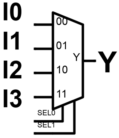
a)
S <= SEL0 & SEL1;
with S select
    Y <= I0 when “00”,
        I1 when “01”,
        I2 when “10”,
        I3 when “11”;
b)
Y <= I0 when SEL0&SEL1 = “00”
else I1 when SEL0&SEL1 = “01”
else I2 when SEL0&SEL1 = “10”
else I3;
c)
Y = I0 when SEL0 =’0’ and SEL1 = ‘0’
else I1 when SEL0 = ‘0’ and SEL1 = ‘1’
else I2 when SEL0 = ‘1’ and SEL1 = ‘0’
else I3;
d)
Y <= (not SEL0 and not SEL1 and I0)
or (not SEL0 and SEL1 and I1)
or (SEL0 and not SEL1 and I2)
or (SEL0 and SEL1 and I3);
Explanation: The general form of a selected signal assignment statement is:
with expression_s select
signal_s <= expression1 [after delay-time] when choice1,
expression2 [after delay-time] when choice2,
. . .
[expression_n [after delay-time] when others];
4. Signals internal to a module are declared at the start of an architecture, before ‘begin’, and can be used only within that architecture.
a) True
b) False
View Answer
Explanation: Port signals have an associated mode (usually in or out), but internal signals do not. A signal used within an architecture must be declared either in a port or in the declaration section of an architecture, but it cannot be declared in both places. A signal declaration has the syntax:
signal list_of_signal_names: type_name [constraint] [:= initial_value];.
5. Constants declared at the start of an architecture can be used anywhere within that architecture.
a) True
b) False
View Answer
Explanation: A constant declaration is similar to a signal declaration. A constant declaration has the syntax:
constant constant_name: type_name [constraint] [:= constant_value];.
6. Predefined unconstrained array types in VHDL include bit_vector and string.
a) True
b) False
View Answer
Explanation: Predefined unconstrained array types in VHDL include bit_vector and string, which
are defined as follows:
type bit_vector is array (natural range <>) of bit;
type string is array (positive range <>) of character;
The characters in a string literal must be enclosed in double quotes. For example,
“This is a string.” is a string literal. The following example declares a constant string1
of type string:
constant string1: string (1 to 29) := “This string is 29 characters.”
A bit_vector literal may be written either as a list of bits separated by commas
or as a string. For example, (‘1’,‘0’,‘1’,‘1’,‘0’) and “10110” are equivalent forms. The
following declares a constant A which is a bit_vector with a range 0 to 5.
constant A: bit_vector(0 to 5) := “101011”;.
7. A VHDL module must consist of an entity and architecture.
a) True
b) False
View Answer
Explanation: To code a complete VHDL module, we must declare all of the input and output
signals using an ‘entity’ declaration, and then specify the internal operation of the
module using an ‘architecture’ declaration.
8. The VHDL entity of a half adder with inputs A, B and outputs Carry and Sum is:
entity HalfAdder is
    port (X,Y: in bit;
    Cout, Sum: out bit);
end FullAdder;
a) True
b) False
View Answer
Explanation: The syntax for a VHDL entity is
entity entity-name is
      [port(interface-signal-declaration);]
end [entity] [entity-name];
The items enclosed in square brackets are optional.
The interface-signal-declaration
normally has the following form:
list-of-interface-signals: mode type [: = initial-value]
{; list-of-interface-signals: mode type [: = initial-value]};
The curly brackets indicate zero or more repetitions of the enclosed clause. Input
signals are of mode in, output signals are of mode out, and bi-directional signals are of mode inout.
The half adder has inputs A, B and outputs Carry and Sum. Hence the entity is
    entity HalfAdder is
        port (X,Y: in bit;
        Cout, Sum: out bit);
    end FullAdder;
a)
architecture half_add_arch of HalfAdder is
begin
    Sum <= A xor B;
    Carry <= A and B;
end half_add_arch;
b)
architecture half_add_arch of HalfAdder is
begin
    Sum <= A or B;
    Carry <= A and B;
end half_add_arch;
c)
architecture half_add_arch of HalfAdder is
begin
    Sum <= A nor B;
    Carry <= A and B;
end half_add_arch;
d)
architecture half_add_arch of HalfAdder is
begin
    Sum <= A nor B;
    Carry <= A nand B;
end half_add_arch;
Explanation:
The truth table of half adder is given by:
| A | B | Sum | Carry |
|---|---|---|---|
| 0 | 0 | 0 | 0 |
| 0 | 1 | 1 | 0 |
| 1 | 0 | 1 | 0 |
| 1 | 1 | 0 | 1 |
From the truth table it can be concluded that the expressions are
Sum = A.B’ + A’.B; this operation is performed by Exclusive-Or gate.
Carry = A.B; this operation is performed by AND gate.
The syntax of architecture:
architecture architecture-name of entity-name is
[declarations]
begin
architecture body
end [architecture] [architecture-name];
In the declarations section, we can declare signals and components that are used
within the architecture. The architecture body contains statements that describe the
operation of the module.
10. Write the VHDL entity for 2-to-1 MUX, called 2_1_mux. The inputs are A1 and A0. S is the select line and Y is the output.
a)
entity 2_1_mux is
    port (A1, A0, S: in bit;
    Y: out bit);
end 2_1_mux;
b)
entity 2_1_mux is
    port (A1, A0: in bit;
    S: inout bit;
    Y: out bit);
end 2_1_mux;
c)
entity 2_1_mux is
    port (A1, A0: in bit;
    S, Y: out bit);
end 2_1_mux;
d)
entity 2_1_mux is
    port (A1, A0: in bit;
    Y: out bit);
end 2_1_mux;
Explanation: The syntax for a VHDL entity is
entity entity-name is
    [port(interface-signal-declaration);]
end [entity] [entity-name];
The items enclosed in square brackets are optional.
The interface-signal-declaration
normally has the following form:
list-of-interface-signals: mode type [: = initial-value]
{; list-of-interface-signals: mode type [: = initial-value]};
The curly brackets indicate zero or more repetitions of the enclosed clause. Input
signals are of mode in, output signals are of mode out, and bi-directional signals are of mode inout.
The 2-to-1 multiplexer has 3 input ports A, B and select line S. S is also an input. The output is Y. Thus, the entity is coded as:
entity 2_1_mux is
      port (A, B, S: in bit;
       Y: out bit);
end 2_1_mux;
11. Write the entity of a 2-to-4 decoder. The entity name is decoder_2_4, input is a bit vector A and output is a bit vector Y.
a)
entity decoder_2_4 is
    port (A: in bit_vector(1 downto 0);
    Y: out bit_vector(3 downto 0));
end decoder_2_4
b)
entity decoder_2_4 is
    port (A: in bit_vector(2 downto 0);
    Y: out bit_vector(4 downto 0));
end decoder_2_4
c)
entity decoder_2_4 is
    port (A: in bit_vector(4 downto 0);
    Y: out bit_vector(2 downto 0));
end decoder_2_4
d)
entity decoder_2_4 is
    port (A: in bit_vector(3 downto 0);
    Y: out bit_vector(1 downto 0));
end decoder_2_4
Explanation: The syntax for a VHDL entity is
entity entity-name is
    [port(interface-signal-declaration);]
end [entity] [entity-name];
The items enclosed in square brackets are optional.
The interface-signal-declaration
normally has the following form:
list-of-interface-signals: mode type [: = initial-value]
{; list-of-interface-signals: mode type [: = initial-value]};
The curly brackets indicate zero or more repetitions of the enclosed clause. Input
signals are of mode in, output signals are of mode out, and bi-directional signals are of mode inout.
The 2-to-4 decoder has 2 inputs and 4 outputs. The bit vector data type is used. Since the counting starts from 0, it ends at N-1.
The keyword ‘downto’ is used.
Sanfoundry Global Education & Learning Series – Logic Design.
To practice all areas of Logic Design, here is complete set of 1000+ Multiple Choice Questions and Answers.
If you find a mistake in question / option / answer, kindly take a screenshot and email to [email protected]